I’m not sure that this design is practical (or sufficiently open) for this use, but I’ll post it here anyway. The unit can do stereo photography and is adjustable remotely.
1 Like
All right, long overdue update… I’ll also link to this post in this camera trap thread.
 Camera trap autopsy pics
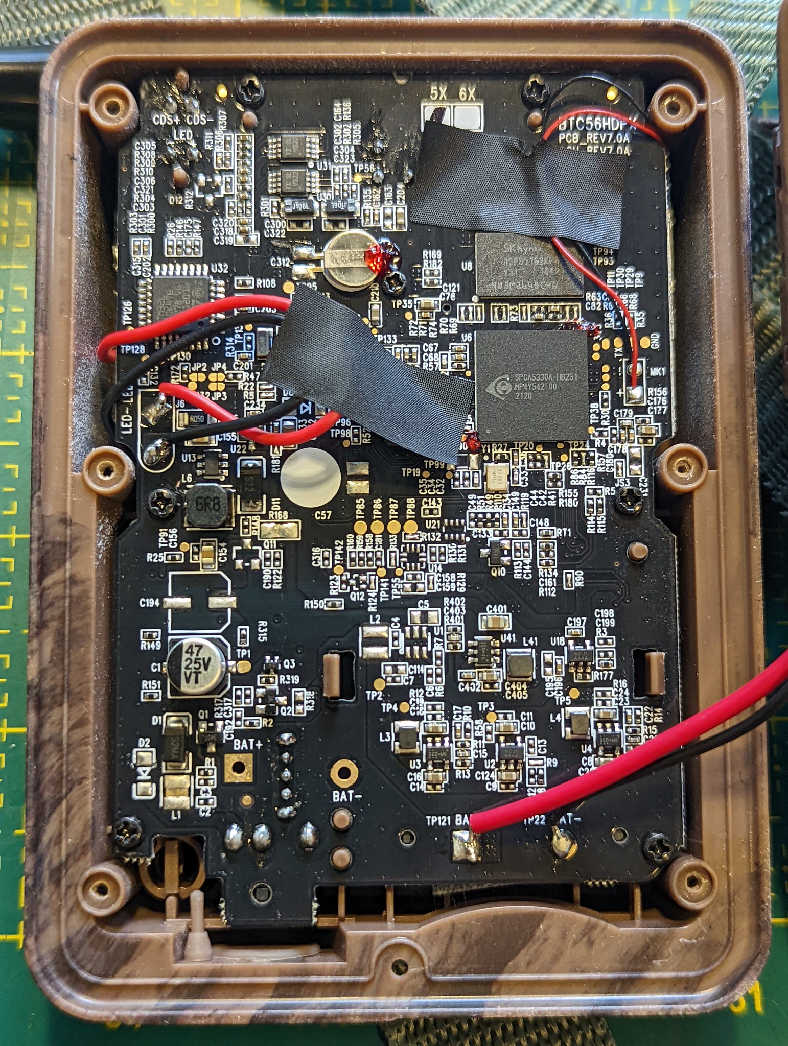
Thanks to @hikinghack who recently conducted an autopsy on one of the camera traps I brought to the camera trap unconference session during our Panama Gathering. It’s the Browning Strike Force HD Pro X (BTC-5HDPX). The goal of the autopsy was to open the camera trap and obtain high resolution images of its PCB board, to see if its trigger circuitry could be tapped into similar to how @Harold did it as described earlier in this thread.
The full set of autopsy photos is in this Flickr album shared under CC BY-SA 4.0. Here is a relevant photo from the album:
@Harold et al.: Any idea if this board could be tapped into??? What’s your assessment?
 Unconference documentation from Panama
Josh generously took notes during our unconference session in Panama. For safekeeping, I made a back up of those notes here:
txti - Fast web pages for everybody (Internet Archive snapshot) (BTW, txti.es is a neat website that let’s you quickly whip up Markdown-based web pages!)
 Notable pieces of hardware
See above for this post on some related work on stereo camera traps. That said, I think @Harold’s approach of linking two existing camera traps together is more practical for field biologists who don’t always have the technical chops to build a camera trap from scratch.
With that in mind, here are a few more pieces of relevant hardware:
- @denisedd’s near-sighted camera traps and @hikinghack’s cool hack to fix it. Now @denisedd could use those camera traps to clearly identify the species of butterfly and track individuals through their markings!
- @jmwright’s posts immediately above this one on LoRa tech and stereo imaging cameras.
- The T-Camera S3 – An ESP32-S3 board with camera, display, PIR motion sensor, and microphone. Shared by @Albercook.
- An “Open source USB C camera with C mount lens, MIPI Sensor, Lattice FPGA, USB 3.0” discussed in this Hacker News thread (project repository).
- EsPiFF: An ESP32 in the Raspberry Pi form factor (also discussed in Hacker News).
- Bee Motion S3 on Crowd Supply - an “open source ESP32-S3 PIR motion sensing board”.
 Relevant scientific papers
I’m reposting below a few links I shared with @Albercook to a few scientific papers that justify the need for a stereo camera trap to obtain spatial data in images to estimate wildlife populations.
Point transect method:
https://besjournals.onlinelibrary.wiley.com/doi/10.1111/2041-210X.12790
The other one I mentioned is the Random Encounter Model which, AFAIU, requires angle data. Here’s the classic paper on the topic:
https://doi.org/10.1111/j.1365-2664.2008.01473.x
If you look at the papers that cite it, you can see more recent developments with the model.
It is inspired by collision rates of molecules in gas models, such as discussed here:
https://doi.org/10.1111/j.1469-185X.2007.00014.x
And in “Assessing the camera trap methodologies used to estimate density of unmarked populations” they give a pretty good review of contemporary methods:
1 Like
Very nice pics. You can make out the 3 PIR sensor pins (through hole) at the top, just left of the black sticky tape.
The fact that the PIE has 3 pins (and not some other number) indicates that they are analogue output (could be this one or this one. This means the electronics are easy to modify to turn the camera into a slave unit, but turning it into a master will require more sleuthing with no guarantee of success. You can see here for tracing details. Briefly, you can apply a voltage at pin 2 to trigger the camera. The circuit here built as a receiver will do just that.
The above is about modifying the electronics. Modifying the enclosure mechanically is a different story. I can’t say anything about that, not having the unit in hand.
2 Likes
A new paper hot off the press about adding LoRa and AI capabilities to camera traps (Whytock et al. 2023).
What’s interesting is not the LoRa or AI stuff, but how they physically modded their camera traps by opening the case and adding a microcontroller, plus adding a “bridge” module. This is described in section 2.1. I really need to give this a read…
1 Like
I’ve talked some with @hpy about this work via email, and I’m putting some information here so that we can keep everything in once place.
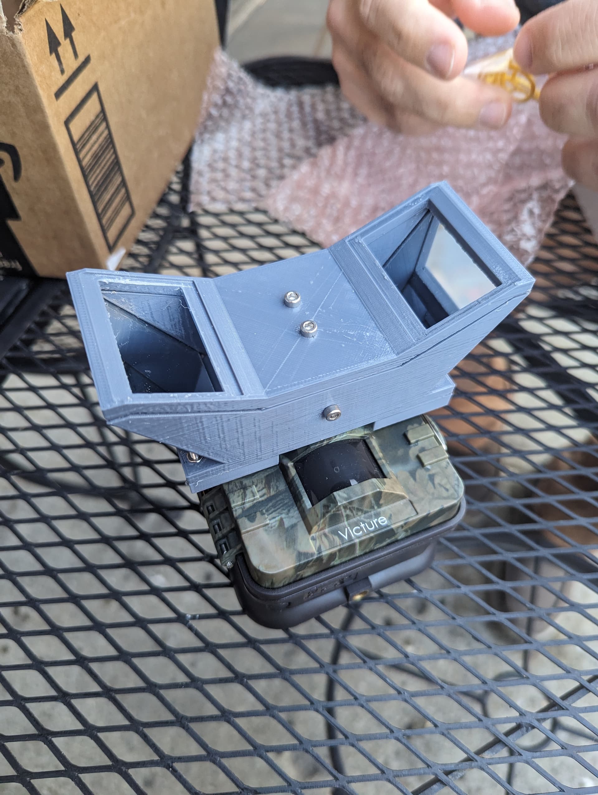
I have been experimenting with the idea of creating a 3D printed sterescope (beam-splitter?) that could be added onto camera traps, kind of like “3D glasses” that would add depth sensing capability.
The goal would be to make this a universal attachment for the widest range of camera traps possible. There is post processing of the images required of course, which could be done with OpenCV (Pen posted this link previously).
https://docs.opencv.org/4.x/dd/d53/tutorial_py_depthmap.html
The current iteration of the 3D printed design “works”, but the mirrors I started with (25 mm) are too small to fit the vertical field of view of my phone’s camera. I have an inexpensive stereoscope that I bought on Amazon, and it uses 30 mm mirrors, which is still not quite big enough.
https://us.amazon.com/Mobile-Stereoscopic-Camera-Universal-External/dp/B09GXZCMLT
The commercial ones that attach to something like a DSLR camera have even larger mirrors.
https://www.bhphotovideo.com/c/product/1023756-REG/kula_kd1d77_camera_lens_attachment_for.html
I have some 50 mm mirrors that I will attempt to use next.
This seems like a promising route, but there are a lot of questions to answer, even after the 3D printed stereoscope attachment is working well.
- Is there a single mirror width that can be used for all camera trap camera lenses/sensors? This value is probably at or above 30 mm, but testing is required.
- What image quality is good enough? This will need testing and practice. By the time you account for the lost image in the center and extremes of the sides, it’s less than a 50/50 split of the camera’s field of view.
- How is a single image going to be processed?
- How will many images be batch-processed?
- How will distance be calibrated in these images, and does it need to be? Will a post/stake have to be placed at a set distance away from the camera trap at every location? What happens if that stake is forgotten or knocked over?
- Can something be designed into the stereoscope hardware to make it easier for an automated image processing system to crop the stereo images properly?
- Currently, a single size of mirror has been purchased (25.4 mm), and the inner mirrors are cut down to the correct size ratio (~19 mm). A 3D printed jig has been created for use with a standard hand-held glass cutter to help with this. Is this acceptable for something that could have to be buildable by makers in large quantities?
- How many different kinds of camera traps do shim adapters have to be created for? The shim adapter goes between the camera trap and the stereoscope and attaches it, and makes sure it is held in the correct position.
- Will all camera traps allow the stereoscope to be attached close enough to the camera lens (about 6 mm), or will some have enclosure features that get in the way?
- What attachment mechanism should be used for these stereoscopes to adapt to the widest range of camera traps and to be user friendly?
- What will the instructions look like? For instance - If stereoscopes are not reasonably level with the horizon, there will be image distortion. Users need to be aware of potential problems like this.
- How will compass data be carried with the images for a camera trap? My understanding is that the direction of movement of animals in the stereo images will be important.
- How will these be sealed against weather? Heat sealed, epoxied, O-rings so that the stereoscopes can be disassembled and repaired? I believe that @jpearce has done some work on heat-sealing for weather-proofing.
- How will these be made robust against animal inflicted damage? Probably just by making the sidewalls thicker and using tougher 3Dprinter filaments/resins. The need to use exotic filaments will cut down on the number of makers available to build these. Anecdotally, I once 3D printed a bird feeder in PLA and the birds ruined it up by pecking at it. PETG is my primary filament these days and I expect it will have less problem with that.
- The inside mirrors probably need to be bevelled at a 45 degree angle to make a clean right angle directly above the camera lens. However, grinding the mirror glass is beyond the skill and equipment of most makers (including me). Should a “good enough” approach be followed, should the instrument try to uphold higher standards, or should documentation be created the supports both use cases?
- How will these units be bench tested? My initial idea was to borrow a foam deer target (used by deer hunters in the US) and stage it near some trees, then take pictures with my phone camera. If those images can be processed, it would help pave the way for field testing.
- How will this instrument be field tested?
- What is the “victory condition” for this project? When will we know that depth/distance data improves wildlife monitoring? Have studies already been done on this using stereoscopic camera traps? If not, that study could be conducted with this stereoscopic attachment.
2 Likes
super cool fun idea!
and for filament, PETG lasts well and takes abuse here in the jungle in panama!
2 Likes
Have any of you ever noticed a camera trap that has a camera sensor that is slightly off-center and/or off-angle relative to the enclosure? I’m getting some unexpected results with my Victure HC200 and have been over my design many times to ensure it’s not the problem. It probably normally doesn’t matter if things aren’t perfectly aligned in a camera trap, but since I am placing an optical device in front of the camera lens, it creates just enough of an effect to be noticeable.
1 Like
Just saw this in the news today, “Amsterdam to use ‘noise cameras’ against too loud cars”:
Quote:
The noise camera consists of a box containing four microphones that can detect precisely where a sound is coming from. The box is connected to a regular speed camera, which takes a photo of the license plate to issue a fine. If the data from the current experiment proves reliable, Amsterdam and other large cities will ask the Cabinet to have the technology certified.
I wonder if this is what @Harold had in mind! ![]()
1 Like
Yes, something similar. Instead of noisy cars, it could be used to take photos of e.g. rare birds. That’s probably more difficult than cars.
1 Like
Adding quick note here to help myself remember this new paper:
Dunkley, K., Dunkley, A., Drewnicki, J., Keith, I., & Herbert-Read, J. E. (2023). A low-cost, long-running, open-source stereo camera for tracking aquatic species and their behaviours. Methods in Ecology and Evolution, 00, 1–8. https://doi.org/10.1111/2041-210X.14151
A stereo camera! But looks like what might be more useful for this thread is the software they developed to process the stereo images, rather than the hardware.
I’ll try to give an update on the camera trap work as soon as I can. Had some interesting meetings recently, plus of course our Experiment.com funding.
1 Like
Here is an article that’s loosely related to this topic where two smartphone cameras are synchronized.
2 Likes
@hikinghack Here is a screenshot of the zip-tie shim for the stereoscope that we talked about, and the stl file is available here.
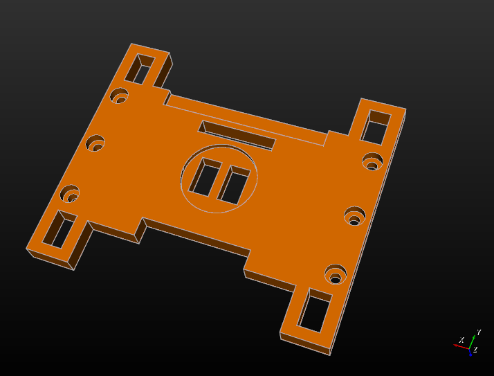
Please let me know if this shim design will work, or if you think it needs to change.
I’ll give some context for everyone else on why I am posting this update:
@hikinghack and I were able to meet up in person this week, and I handed off a stereoscope and camera trap that is headed for Panama. This is the stereoscope that is part of this project on Experiment.com.
I was glad to be able to be able to send this with @hikinghack since shipping things outside the mainland US can be expensive and a pain. I think @hpy is working on a post about some of our experiences and tying it in with distributed manufacturing.
A design change to the stereoscope’s shim came out of the discussion during the meetup. Rubber bands have typically been used to secure the stereoscope to the camera trap, but in the jungle in Panama there are microbes that will eat those rubber bands quickly. So the shim I posted about above is designed to work with zip ties instead.
I am excited to see what @hpy and @hikinghack do with this new opportunity for collaboration.
2 Likes
That looks great!
2 Likes