3D Glasses for Wildlife Camera Traps on Experiment.com

We recently used 3D scanning as a tool to help share design components between globally distributed team members, and I created a lab note describing how to process the scans for use in CAD programs.

Even if you are not interested in the technical parts of the post, it might still be worth reading the introduction. The need we had has probably been experienced by others on this forum.

2 Likes

There is more conversation here, but I felt like we were starting to hijack that thread which was not dedicated to this project. So I will continue updates here so that they are publicly available. Tagging @hpy @julianstirling @hikinghack @jpearce

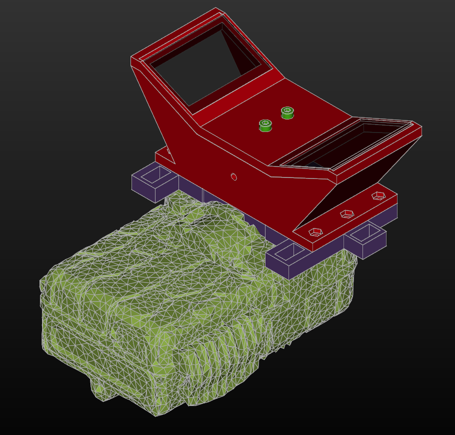
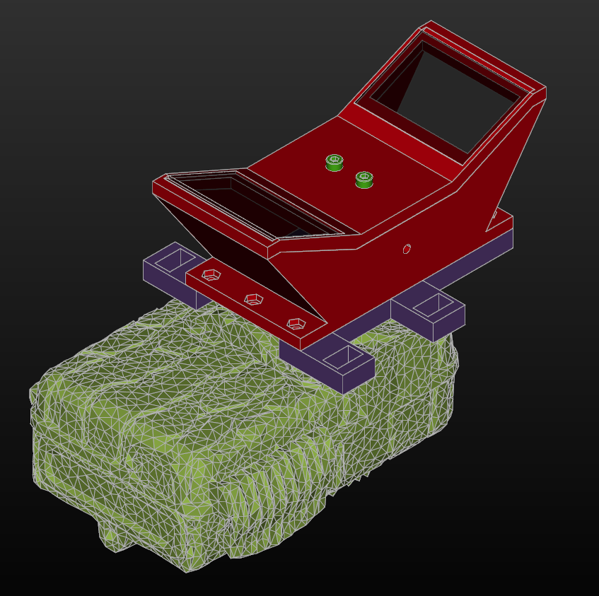
After making the zip tie shim modification for @hikinghack to use in Panama (rubber bands were not practical for field use), @hpy expressed interest in a similar shim for the camera trap being used in the UK. Below are links to the STL files for the two different orientations, and images showing what they look like.

Horizontal Mount Zip Tie Shim

STL Link

Vertical Mount Zip Tie Shim

STL Link

1 Like

@hpy and I will hopefully be doing some camera trapping pretty soon. We will feedback when we can!

2 Likes

Is the shim a custom fit for the camera in question? If so, would it be possible to make a more generic shim with a long skirt that you mould (the skirt part) onto any camera with a hair dryer? Assuming you’re using PLA.

1 Like

One possible option for a more generic shim may be to have a few nut traps in a shim. You can then use long bolts to approximately level the shim. Zip-tie it, and then tighten the bolts slightly to finally level it.

Something a bit like this:

Probably would be better to have some 3D printed ends on the screws to protect the camera. So more like:

@jmwright how sensitive are the glasses to the camera to glasses distance?

1 Like

Each shim is currently custom, yes. A generic shim would be nice, as both you and @julianstirling have suggested. PLA will not work for @hikinghack in the Panamanian jungle, but it may work for the deployment Julian and @hpy are planning in the UK. I only print in PETG these days, but there is nothing in the CAD models that creates a material requirement.

If you are interested in trying this stereoscope design out for yourself, I can model a shim with a skirt that you can try. It will probably take a few iterations to get something that will work. I’m happy to provide support during the manufacturing and assembly process as well of course.

The documentation for the stereoscope is here. The mirror cutting may seem intimidating to some people, but it is not hard. I was able to do it with no glass cutting experience and cut the glass by hand using an inexpensive tool. I have also provided a 3D printable cutting guide and break in the repository to simplify the process. The entire build is pretty low complexity.

Cool! I think @hpy has one ready to go for the first trap. I think PLA will be fine as it will be going inside the building to try to photo the bats. We do sometimes get birds in the building.

We should also think about putting one in the tailrace of the mill, we have a couple of beautiful kingfishers living there, we also get egrets and herons visiting quite often, we also think there are otters, but we are not certain.

2 Likes

The current design uses nut traps everywhere, and it would not be hard to create a shim with push-pull nut traps as you have shown in your diagrams.

The distance of the stereoscope from the camera lens is not overly critical. It seems to only change the amount of the field of view that is filled.

As far as alignment in other axes, I am going to switch to aircraft terminology because I feel it is the best way for me to explain. This diagram will help show the terminology I am using. Picture the horizontally mounted stereoscope in my image above as an airplane flying away from the lens of the camera with its wings level.

The stereoscope is very sensitive to Roll. With just a small amount, the stereo images lose a lot of the parallel alignment that I assume they need to be processed properly.

The stereoscope is somewhat sensitive to Yaw, but I think it takes more of it to cause a problem than with Roll. Interestingly, the Victure camera trap that @hikinghack has exhibits an issue where it seems to have the camera sensor mounted a degree or two off-angle, which causes a little Yaw effect with the stereoscope. I actually experimented in creating a shim that corrected for this, but eventually decided I did not have the time to keep experimenting with it. Having adjustment screws would allow things like this to be compensated for.

The stereoscope is probably least sensitive to Pitch, with Roll and Yaw being more critical.

So having screw jacks like you have pictured might allow for a generic shim at the expense of being more complicated to adjust properly.

Camera traps vary so greatly in configuration that on many models it will be hard/impossible to eliminate the gap between the camera trap and the stereoscope. In my testing, light leak in that gap can cause problems with the images. That is just anecdotal though, I never did any testing specifically on this. I am still not clear on whether or not these stereoscopes need to be sealed, or just cleaned periodically. I did not glue the clear lens covers in the stereoscopes that @hpy and @hikinghack have for that reason. Maybe testing can be done to see how much those gaps really affect image quality, and how likely it is for dirt and insects to foul up images.

I should also note that I hope to work on a periscope mount for the stereoscope (as suggested by @jpearce elsewhere). The problem with the current stereoscope configuration is that it will block IR emitters, PIR sensors, etc on some camera traps. I will probably also try to scale the stereoscope down again. You can see early pictures in the repository where I used 25mm mirrors instead of 50mm mirrors. This was a nice, compact design, but led to very small stereo images. My fear was that the stereo images would be too small to process properly, but that was just a guess. I need guidance from researchers on what works and what does not.

Everything in the design is up for change right now. I am hopeful that more feedback from the field will show what works and what does not, leading to a more production-ready design.

I am also going to drop this link here so that everyone has it. @hikinghack did a good job of explaining that software to me, but I’m still not sure I totally understand. I think that we can take a series of images when setting a camera trap up in a certain location. Then those baseline images can be used to make it easier to process the wildlife images later.

Thanks Jeremy, it looks like you’ve got your bases covered. Do you know if there may be an issue with light leaks? BTW is your modelling done in FreeCAD?

2 Likes

There are no light leaks (that I’m aware of) with the current design that requires a custom shim per camera trap.

The modeling is all done using CadQuery, which is an open source Python API for creating CAD models. CadQuery and FreeCAD use the same CAD kernel, and so it is possible to exchange data back and forth. Within the last few months I wrote a plugin for CadQuery that allows it to import and modify parametric FreeCAD models.

2 Likes

Camera traps going into the waterwheel:

We hope to get photos of the bats in the building, and have a camera in the tail race to hopefully photograph the kingfishers and other birds.

2 Likes

It’s so great to see that being deployed! Thanks for sharing. I’m ready for more feedback on the hardware design, whenever you two have any. I already have an experimental version of the stereoscope in progress that incorporates some of the feedback from this thread.

So far the main feedback I have is:

  • We had the elastic band version that we know is old… The front was a bit wibbly, but this is now fixed.
  • The camera is a bit front heavy. This is probably because we were just trying to do some test positioning with it sitting on a bench and it liked to fall forward. This was easily solved by screwing it to some wood.

In a week or two I will hopefully have some images to share so we can assess performance.

Thanks

1 Like

Great, thanks.

  • If we can get usable stereo images when using 25mm mirrors, that should help with multiple issues, including being front heavy. More to come on that as I try to adapt an old 25mm design to incorporate everything we’ve already learned.
  • I am not sure how much camera attachment screws vary between region, but I have a tripod that has a mounting shoe for cameras that threads into the bottom of that camera trap. If you have a tripod, you could try that. It makes it convenient to vary height, angle, etc during testing as well.

We didn’t have a tri-pod to hand. Tri-pods screws are standardised to a 1/4"-20 UNC screw. Which does make it harder to find other screws for mounting outside the US. Luckily the workshop we had on site has screws pre-dating the introduction of metric in the UK (We also have Whitworth screws pre-dating UNC, we even have screws pre-dating the concept of screw standardisation in the 1840s!)

1 Like