Depth Sensing Technologies for Camera Traps

Oh I see @Harold! That’s simpler than I thought. If it’s hot rods you want to photograph, you can set the trigger threshold to very high dB, thereby prevent most false triggers. And since the camera traps will be deployed roadside, probably with sufficient sun exposure and relatively easy to service, power consumption is probably not a problem. So I think what you’re suggesting is almost like a speed camera but acoustically instead of optically triggered…

Just curious: Do you think modding an Audiomoth into the acoustic trigger would help? Or just building something from scratch using the PH0645 microphone?

As for stereo camera traps…

Indeed, the motion sensors in camera traps are custom designed to have optimised trigger thresholds and detection angles. Several people I know have tried off the shelf PIR motion detectors, but they are usually waaaaaay too sensitive and you get a mountain of false-triggered images. So as a first step, I think building on an existing camera trap’s trigger would be better.

I did briefly consider setting up two camera traps side-by-side to obtain stereo images, but I think you suggested the critical point which is for both to be trigger simultaneously by the motion sensor on one camera trap.

In any case, I think the biggest core concept of both of our ideas (plus the BoomBox) is to tap into the triggering circuitry of existing camera traps. Right?

The closest thing I am aware for understanding that circuitry is this documentation of the BoomBox. Pages 12 & 13 links to Freaklabs’s documentation on how to tap into the motion sensors in 4 different models of camera traps. I’ve used camera traps extensively in the field, but don’t have the electronics expertise to fully understand if the information in that documentation is enough for us to plan next steps.

Are you or someone able to assess this documentation???

Excited to continue this conversation. I’m already learning lots from you @Harold!

| hpy
May 26 |

  • | - |

Oh I see @Harold! That’s simpler than I thought. If it’s hot rods you want to photograph, you can set the trigger threshold to very high dB, thereby prevent most false triggers. And since the camera traps will be deployed roadside, probably with sufficient sun exposure and relatively easy to service, power consumption is probably not a problem. So I think what you’re suggesting is almost like a speed camera but acoustically instead of optically triggered…

Yes that’s right!

Just curious: Do you think modding an Audiomoth into the acoustic trigger would help? Or just building something from scratch using the PH0645 microphone?

I think the Audiomoth could probably be modified to be an acoustic trigger, but I don’t think it will be easy to integrate an I2S mic. The native mic is a MEMS PDM unit, and it also has an analog port. If the mic – regardless of output type – is calibrated, then it can be used. But then, something like https://sea.banggood.com/Voice-Detection-Sensor-Module-Sound-Recognition-Module-High-Sensitivity-Sensor-Microphone-Module-DC-3_3V-5V-p-1357680.html could also be used, if one were to go to the trouble of calibrating it.

As for stereo camera traps…

[…]

In any case, I think the biggest core concept of both of our ideas (plus the BoomBox) is to tap into the triggering circuitry of existing camera traps. Right?

The closest thing I am aware for understanding that circuitry is this documentation of the BoomBox. Pages 12 & 13 links to Freaklabs’s documentation on how to tap into the motion sensors in 4 different models of camera traps. I’ve used camera traps extensively in the field, but don’t have the electronics expertise to fully understand if the information in that documentation is enough for us to plan next steps.

Visit Topic or reply to this email to respond.

I had not seen this doc! That is exactly correct, the 2 cameras’ PIR sensor output pins need to be combined. Usually the PIR’s output pin goes to a diode or transistor, and it is the output of this diode or transistor that should be wired together (and the grounds of both cameras need to be connected also). Then the slave unit can have its PIR sensor blindfolded so it never triggers. I do believe that’s all: stereo camera trap!

1 Like

Thank you @Harold, a few more questions if I may. :slight_smile:

1.

You mentioned creating a small PCB, one that might even fit inside a camera trap’s casing. Might there be value in turning it into a generalised interface board between the triggering circuitry in a camera trap and external components like your acoustic trigger, other camera traps, stereo cameras, speakers, etc.?

So something like this:

 ┌─────────────────┐        ┌───────────────────┐        ┌─────────────────────┐
 │                 │        │                   │        │                     │
 │ camera trap     │◄───────┤ trigger interface │◄───────┤                     │
 │                 │        │                   │        │ external components │
 │ trigger circuit ├───────►│ board             ├───────►│                     │
 │                 │        │                   │        │                     │
 └─────────────────┘        └───────────────────┘        └─────────────────────┘

The board would expose pins or other ports to serve as a standard interface for external components to either trigger, or be triggered by, a connected camera trap. So, you would connect your acoustic detector to this board and cover the camera trap’s PIR sensor. And for me, I would connect another camera trap to this board.

In other words, this board would give a camera trap the generalised ability to accept expansions. Would you be interested in figuring this out?

2.

Also, based on what you’ve seen in the BoomBox documentation, do you think hacking into the PIR sensor circuits in a camera trap is a difficult job? I used to do electronics, but haven’t soldered anything in 15+ years! I am comfortable opening the case and drilling holes as described in the documentation, but don’t know if my rusty soldering skills (or lack thereof) are up to the job…

3.

Is there a difference in where to tap into a camera trap’s circuitry depending on if you want to use the camera as a trigger vs triggering it externally?

You mentioned creating a small PCB, one that might even fit inside a camera trap’s casing. Might there be value in turning it into a generalised interface board between the triggering circuitry in a camera trap and external components like your acoustic trigger, other camera traps, stereo cameras, speakers, etc.?

So something like this:

 ┌─────────────────┐        ┌───────────────────┐        ┌─────────────────────┐

 │                 │        │                   │        │                     │

 │ camera trap     │◄───────┤ trigger interface │◄───────┤                     │

 │                 │        │                   │        │ external components │

 │ trigger circuit ├───────►│ board             ├───────►│                     │

 │                 │        │                   │        │                     │

 └─────────────────┘        └───────────────────┘        └─────────────────────┘

The board would expose pins or other ports to serve as a standard interface for external components to either trigger, or be triggered by, a connected camera trap. So, you would connect your acoustic detector to this board and cover the camera trap’s PIR sensor. And for me, I would connect another camera trap to this board.

In other words, this board would give a camera trap the generalised ability to accept expansions. Would you be interested in figuring this out?

This is exactly what I planned to do, since it will allow my acoustic recorder to trigger one or more camera traps simultaneously. I was thinking that a 2.5mm audio TS jack would make a suitable signal interface. The interface PCB I mentioned would be glued on the CT’s PCB anywhere convenient, and leads brought out to CT’s circuitry. It may also do some pulse conditioning and prevent continuous triggering.

Any kind of device can listen in on the trigger signal, and they could flash lights or make sounds like Boombox does. One post on wildlabs describes using flailing inflatable tube advertising humanoids as scarecrows to address human-wildlife conflict issues. I’ve heard of swinging thorny branches around for the same purpose.

2.

Also, based on what you’ve seen in the BoomBox documentation, do you think hacking into the PIR sensor circuits in a camera trap is a difficult job? I used to do electronics, but haven’t soldered anything in 15+ years! I am comfortable opening the case and drilling holes as described in the documentation, but don’t know if my rusty soldering skills (or lack thereof) are up to the job…

No, I don’t think it will be difficult. The skill is not hard to pick up.

3.

Is there a difference in where to tap into a camera trap’s circuitry depending on if you want to use the camera as a trigger vs triggering it externally?

No, no difference. The same surgery is performed on all CTs. The signal is active low and is pulled high by a resistor i.e. idles high (let’s say, or we could flip the polarity). Any 1 or more CTs or external triggers can pull it low simultaneously or sequentially or at any time, and this causes ALL CTs to trigger on the falling edge. The only difference between a master and slave CT is the slave will have its PIR window physically blacked out or otherwise disabled so it cannot be a triggering source. In practice I think there should be only 1 master CT, because I don’t know how multiple CTs will behave if 2 triggers occur very close together. This cannot happen with 1 master, but it could with 2 or more.

The trigger signal can also be broadcast wirelessly. The repeater kit would work like a wireless doorbell. There may be uses for this long range trigger signal.

I’m hampered by not having access to a wide variety of camera traps. I can deduce what all CT trigger circuits ought to look like, and I can verify it against my own cheap CT, but I can’t verify it generally. I can use some help here.

1 Like

@hikinghack and I talked about the camera trap work after the GOSH Community Council meeting today. He’s happy to help do some of the surgery we’ve discussed, and also some field testing! Thanks @hikinghack!

We also talked about how OpenCV can help once we obtain the images, namely:

This is exactly what I planned to do, since it will allow my acoustic recorder to trigger one or more camera traps simultaneously. I was thinking that a 2.5mm audio TS jack would make a suitable signal interface. The interface PCB I mentioned would be glued on the CT’s PCB anywhere convenient, and leads brought out to CT’s circuitry. It may also do some pulse conditioning and prevent continuous triggering.

Great! My electronics knowledge is not up to par, but let me know if or how I can assist here.

No, I don’t think it will be difficult. The skill is not hard to pick up.

Good to know.

The trigger signal can also be broadcast wirelessly. The repeater kit would work like a wireless doorbell. There may be uses for this long range trigger signal.

Which, I guess, would be connected to this putative PCB that you’re proposing!

No, no difference. The same surgery is performed on all CTs.

Also, great. Thanks for the explanation.

I’m hampered by not having access to a wide variety of camera traps. I can deduce what all CT trigger circuits ought to look like, and I can verify it against my own cheap CT, but I can’t verify it generally. I can use some help here.

At the discussion today, I expressed a willingness to pitch in a buy a few camera traps for this effort. I will probably buy the cheapest one listed in Freaklab’s BoomBox documentation. Would it help you @Harold if we send you some close up photos of the circuitry once the cases are opened? Or should I send one of the camera traps to you?

While I would certainly love to get my hands on more kit, another option is to have existing owners of camera traps examine their own equipment with a cheap multimeter.

I think I’ll make a simple video explaining how to do this. Basically it’s about locating the output pin of the PIR sensor and tracing (with a multimeter) where it goes. I expect we’ll trade a few closeup photos as we work through this process together (over the forum?) but at the end of this we should have a well-annotated photo that will aid in modifying that particular model of camera trap.

This info will also help in deciding the polarity of the trigger signal. Open collector active low is the obvious choice, but most PIR output pins are active high. This is easy to invert, but it’s easier to not have to invert.

Once that is decided, the interface PCB can be made.

I’m in the middle of field trials right now so the earliest that I can possibly get around to starting this is next week.

1 Like

I’ve been slowly moving this forward and here’s a loooooong overdue update on where things are from my perspective.

Open Hardware Researchers group meeting June 2022

On 2022-06-09, I presented the ideas we discussed in this thread to the Open Hardware Researchers group hosted by @jarancio, thanks for letting me share! Here’s a summary from that meeting based on these notes.

Possible resources/sources of support:

Stereo lenses add on??

Instead of a electronics-based solution as we’ve discussed so far, @jpearce suggested also trying adding “binoculars” in front of the camera lens to give it stereo vision. Essentially the single camera lens would “see” two side-by-side images, which you can then post-process with something like OpenCV. There are even clip-on stereo lenses for smartphones like these:

Also, @jpearce mentioned that now lenses can now be 3D-printed with great precision:

I haven’t tried this approach yet, but I think @jmwright got one of those clip-on lenses and a few components. From what I can tell, the challenge is that these clip-on lenses are not perfectly aligned, so the image seen by the camera sensor can be blurry, a bit off, and have various other artefacts. I suspect this could be solved by “personalising” the binocular lenses to match the dimensions of a camera trap, but this will have to be done for each camera trap model. Happy to hear what @jmwright thinks. IMO this binocular add-on approach and the stereo camera add-on approach can be pursued in parallel. And if we all get to meet in Panama (see below), then we can compare notes and tinker in person!

other notes from meeting

GOSH forum threads (including this one):

Wildlabs thread where I asked @akiba about their BoomBox work, including how they hacked into cameras:

After the stereo images are captured, OpenCV can be used to process them into depth maps (this is where I can try to help by hacking the code), e.g.:

Field test

@hikinghack has generously offered to hack together a pair of side-by-sdie camera traps to get them to trigger simultaneously (see earlier posts in this thread for details). I’ve got in touch with a supplier, NatureSpy, who has kindly offered to give me a discount.

@Harold also kindly offered to field test in Singapore where - even if wildlife is not within easy reach - human or canine subjects could be used to get a depth image.

I think what I need to do now is to procure enough cameras so we can at least get the ball rolling on hacking them! I also need to figure out exactly which camera trap buy from them, and consider the international shipping costs/import taxes.

Add-on interface module

I’d like to re-iterate my love for @Harold’s concept of creating an add-on interface module for camera traps (see this post above). This module would be tied into the camera’s triggering mechanism so that we either trigger the camera from an external source (including from another camera), or use the camera to trigger something else, both would be mediated by this add-on.

@Harold has already sketched out how such a PCB could be designed and examined a camera trap’s internal circuitry a bit.

Also see this post about how the BoomBox project examined the circuitry.

Workshop at Panama Gathering!?

After recent email threads with @Harold and @hikinghack, I think we’re hoping to start doing some stuff now, and do a show and tell about where we are with this stereo camera trap idea at the GOSH Gathering in Panama in late October 2022. Additionally, @Harold is happy to demo hacking into the triggering mechanism of camera traps as part of this workshop.

Eventually write this up to be published somewhere…

The academic in me can’t help but think about publishing our results in a peer-reviewed paper(s). Off the top of my head, I can envision the following putative papers:

  • Conceptual review that looks at existing depth-sensing tech and describing the need for it in ecological monitoring with camera traps (see this post, which @laola helped me think through). This review could end with presenting the concepts discussed in this thread?
    • Alternatively, presenting our novel concepts could be in a separate, opinion piece/perspective article that some scientific journals have…
  • Short paper, maybe in the Journal of Open Hardware/Hardware X (???), describing @Harold’s interface add-on once we’ve made it.
  • If we can rig more of these stereo camera trap together to run a proper ecological survey, then we can probably publish the results and compare them to other survey methods to see if we get comparable results. This is potentially publishable in a ecological journal.
  • If we manage to develop and fabricate the stereo camera add-on, then it might also be publishable in the Journal of Open Hardware/Hardware X?

I’d be curious what the academics among us think of this…

What do you think?

Any feedback is appreciated. It’d be cool if we can do something in Panama together!

There’s probably more stuff I forgot to include in this post, please remind me!

Thanks @hikinghack, @Harold, @jarancio, @jpearce, @jmwright, @laola.

2 Likes

Hi everyone, it’s been a while but here’s another update on what’s been going on with the camera trap stuff…

Session(s) at 2022 Gathering in Panama!

@Harold, @hikinghack, @laola and I hope to run a session or two at our Gathering in Panama this week. Here are some ideas:

  1. Harold will show and tell a set up for linking two camera traps together to obtain stereo images. See earlier in this thread for details.
  2. Laura will brainstorm with us what kinds of artistic creations could come from camera trap.

I’ll do my best to hack together some code to turn images from Harold’s stereo camera set up into a depth map with which we can judge the distance of objects in it.

Other developments

Through Wildlabs, I tuned into a series of recent talks on camera traps and artificial intelligence. There’s a research group in Germany that has been publishing their work on distance estimation from camera trap data, including using videos from just one camera, or building their own stereo camera trap from scratch. Looks pretty amazing, though I don’t understand the details of the artificial intelligence techniques they used.

That said, I really like Harold’s approach because most ecologists/scientists don’t have the skills, time, or resouces to manufacture camera traps at scale. But Harold’s set up is much easier, especially if the idea of a common interface board could be realised.

And who knows, maybe one day we can try Joshua’s idea of letting a camera trap wear binocular “glasses”, too!

Also, I’m noting here that there was a brief thread with @jmwright about wireless connections for mobile sensors. Not directly related to depth-sensing but wanted to put it here so I don’t lose track of it.

1 Like

Regarding LoRa: I’ve seen multiple articles and products that combine camera traps and LoRa since I posted that question. Covert LoRa Trail Camera System (LoRa LB-V3) - Verizon

1 Like

I’m not sure that this design is practical (or sufficiently open) for this use, but I’ll post it here anyway. The unit can do stereo photography and is adjustable remotely.

1 Like

All right, long overdue update… I’ll also link to this post in this camera trap thread.

:fork_and_knife: Camera trap autopsy pics

Thanks to @hikinghack who recently conducted an autopsy on one of the camera traps I brought to the camera trap unconference session during our Panama Gathering. It’s the Browning Strike Force HD Pro X (BTC-5HDPX). The goal of the autopsy was to open the camera trap and obtain high resolution images of its PCB board, to see if its trigger circuitry could be tapped into similar to how @Harold did it as described earlier in this thread.

The full set of autopsy photos is in this Flickr album shared under CC BY-SA 4.0. Here is a relevant photo from the album:

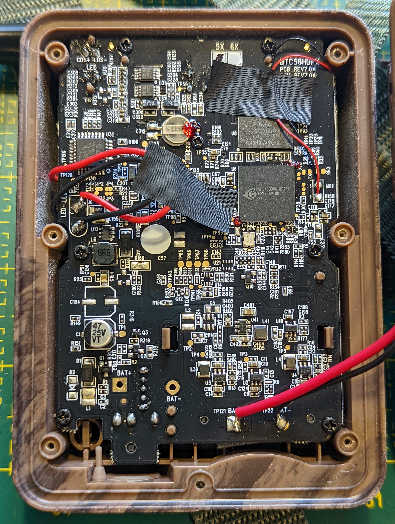
@Harold et al.: Any idea if this board could be tapped into??? What’s your assessment?

:scroll: Unconference documentation from Panama

Josh generously took notes during our unconference session in Panama. For safekeeping, I made a back up of those notes here:

GOSH 2022 camera trap session notes (Internet Archive snapshot) (BTW, txti.es is a neat website that let’s you quickly whip up Markdown-based web pages!)

:artificial_satellite: Notable pieces of hardware

See above for this post on some related work on stereo camera traps. That said, I think @Harold’s approach of linking two existing camera traps together is more practical for field biologists who don’t always have the technical chops to build a camera trap from scratch.

With that in mind, here are a few more pieces of relevant hardware:

:newspaper: Relevant scientific papers

I’m reposting below a few links I shared with @Albercook to a few scientific papers that justify the need for a stereo camera trap to obtain spatial data in images to estimate wildlife populations.

Point transect method:

https://besjournals.onlinelibrary.wiley.com/doi/10.1111/2041-210X.12790

The other one I mentioned is the Random Encounter Model which, AFAIU, requires angle data. Here’s the classic paper on the topic:

https://doi.org/10.1111/j.1365-2664.2008.01473.x

If you look at the papers that cite it, you can see more recent developments with the model.

It is inspired by collision rates of molecules in gas models, such as discussed here:

https://doi.org/10.1111/j.1469-185X.2007.00014.x

And in “Assessing the camera trap methodologies used to estimate density of unmarked populations” they give a pretty good review of contemporary methods:

https://doi.org/10.1111/1365-2664.13913

1 Like

Very nice pics. You can make out the 3 PIR sensor pins (through hole) at the top, just left of the black sticky tape.

The fact that the PIE has 3 pins (and not some other number) indicates that they are analogue output (could be this one or this one. This means the electronics are easy to modify to turn the camera into a slave unit, but turning it into a master will require more sleuthing with no guarantee of success. You can see here for tracing details. Briefly, you can apply a voltage at pin 2 to trigger the camera. The circuit here built as a receiver will do just that.

The above is about modifying the electronics. Modifying the enclosure mechanically is a different story. I can’t say anything about that, not having the unit in hand.

2 Likes

A new paper hot off the press about adding LoRa and AI capabilities to camera traps (Whytock et al. 2023).

What’s interesting is not the LoRa or AI stuff, but how they physically modded their camera traps by opening the case and adding a microcontroller, plus adding a “bridge” module. This is described in section 2.1. I really need to give this a read…

1 Like

I’ve talked some with @hpy about this work via email, and I’m putting some information here so that we can keep everything in once place.

I have been experimenting with the idea of creating a 3D printed sterescope (beam-splitter?) that could be added onto camera traps, kind of like “3D glasses” that would add depth sensing capability.

The goal would be to make this a universal attachment for the widest range of camera traps possible. There is post processing of the images required of course, which could be done with OpenCV (Pen posted this link previously).

https://docs.opencv.org/4.x/dd/d53/tutorial_py_depthmap.html

The current iteration of the 3D printed design “works”, but the mirrors I started with (25 mm) are too small to fit the vertical field of view of my phone’s camera. I have an inexpensive stereoscope that I bought on Amazon, and it uses 30 mm mirrors, which is still not quite big enough.

https://us.amazon.com/Mobile-Stereoscopic-Camera-Universal-External/dp/B09GXZCMLT

The commercial ones that attach to something like a DSLR camera have even larger mirrors.

https://www.bhphotovideo.com/c/product/1023756-REG/kula_kd1d77_camera_lens_attachment_for.html

I have some 50 mm mirrors that I will attempt to use next.

This seems like a promising route, but there are a lot of questions to answer, even after the 3D printed stereoscope attachment is working well.

  • Is there a single mirror width that can be used for all camera trap camera lenses/sensors? This value is probably at or above 30 mm, but testing is required.
  • What image quality is good enough? This will need testing and practice. By the time you account for the lost image in the center and extremes of the sides, it’s less than a 50/50 split of the camera’s field of view.
  • How is a single image going to be processed?
  • How will many images be batch-processed?
  • How will distance be calibrated in these images, and does it need to be? Will a post/stake have to be placed at a set distance away from the camera trap at every location? What happens if that stake is forgotten or knocked over?
  • Can something be designed into the stereoscope hardware to make it easier for an automated image processing system to crop the stereo images properly?
  • Currently, a single size of mirror has been purchased (25.4 mm), and the inner mirrors are cut down to the correct size ratio (~19 mm). A 3D printed jig has been created for use with a standard hand-held glass cutter to help with this. Is this acceptable for something that could have to be buildable by makers in large quantities?
  • How many different kinds of camera traps do shim adapters have to be created for? The shim adapter goes between the camera trap and the stereoscope and attaches it, and makes sure it is held in the correct position.
  • Will all camera traps allow the stereoscope to be attached close enough to the camera lens (about 6 mm), or will some have enclosure features that get in the way?
  • What attachment mechanism should be used for these stereoscopes to adapt to the widest range of camera traps and to be user friendly?
  • What will the instructions look like? For instance - If stereoscopes are not reasonably level with the horizon, there will be image distortion. Users need to be aware of potential problems like this.
  • How will compass data be carried with the images for a camera trap? My understanding is that the direction of movement of animals in the stereo images will be important.
  • How will these be sealed against weather? Heat sealed, epoxied, O-rings so that the stereoscopes can be disassembled and repaired? I believe that @jpearce has done some work on heat-sealing for weather-proofing.
  • How will these be made robust against animal inflicted damage? Probably just by making the sidewalls thicker and using tougher 3Dprinter filaments/resins. The need to use exotic filaments will cut down on the number of makers available to build these. Anecdotally, I once 3D printed a bird feeder in PLA and the birds ruined it up by pecking at it. PETG is my primary filament these days and I expect it will have less problem with that.
  • The inside mirrors probably need to be bevelled at a 45 degree angle to make a clean right angle directly above the camera lens. However, grinding the mirror glass is beyond the skill and equipment of most makers (including me). Should a “good enough” approach be followed, should the instrument try to uphold higher standards, or should documentation be created the supports both use cases?
  • How will these units be bench tested? My initial idea was to borrow a foam deer target (used by deer hunters in the US) and stage it near some trees, then take pictures with my phone camera. If those images can be processed, it would help pave the way for field testing.
  • How will this instrument be field tested?
  • What is the “victory condition” for this project? When will we know that depth/distance data improves wildlife monitoring? Have studies already been done on this using stereoscopic camera traps? If not, that study could be conducted with this stereoscopic attachment.
2 Likes

super cool fun idea!

and for filament, PETG lasts well and takes abuse here in the jungle in panama!

2 Likes

Have any of you ever noticed a camera trap that has a camera sensor that is slightly off-center and/or off-angle relative to the enclosure? I’m getting some unexpected results with my Victure HC200 and have been over my design many times to ensure it’s not the problem. It probably normally doesn’t matter if things aren’t perfectly aligned in a camera trap, but since I am placing an optical device in front of the camera lens, it creates just enough of an effect to be noticeable.

1 Like

Just saw this in the news today, “Amsterdam to use ‘noise cameras’ against too loud cars”:

Quote:

The noise camera consists of a box containing four microphones that can detect precisely where a sound is coming from. The box is connected to a regular speed camera, which takes a photo of the license plate to issue a fine. If the data from the current experiment proves reliable, Amsterdam and other large cities will ask the Cabinet to have the technology certified.

I wonder if this is what @Harold had in mind! :sweat_smile:

1 Like

Yes, something similar. Instead of noisy cars, it could be used to take photos of e.g. rare birds. That’s probably more difficult than cars.

1 Like

Adding quick note here to help myself remember this new paper:

Dunkley, K., Dunkley, A., Drewnicki, J., Keith, I., & Herbert-Read, J. E. (2023). A low-cost, long-running, open-source stereo camera for tracking aquatic species and their behaviours. Methods in Ecology and Evolution, 00, 1–8. https://doi.org/10.1111/2041-210X.14151

A stereo camera! But looks like what might be more useful for this thread is the software they developed to process the stereo images, rather than the hardware.

I’ll try to give an update on the camera trap work as soon as I can. Had some interesting meetings recently, plus of course our Experiment.com funding.

1 Like

Here is an article that’s loosely related to this topic where two smartphone cameras are synchronized.

2 Likes