Hi all, for those of you interested in 3D printing, particularly printing parts that you then screw together, we have a test object that it would be interesting to share with you all. The #OpenFlexure project uses “self tapping” holes in printed parts. We’d like to hear from people with different printers to ours how well these works - test object and Google form link here:
Very cool. I’ll have a go at this. We currently use tri-lobed self tapping screws designed for use in plastic moldings. They form threads (rather than cutting) in the same way as forcing a standard screw into a triangular hole. That’s a really good idea…
The reason we use thread forming screws for 3D prints is that the manufacturing part of the company uses them - so there are lots available for R&D to use! the brand we use is Taptite. They just work in a simple cylindrical hole. But the idea of using a triangular hole is so great!
Love the flexure microscope stage. I’m a big fan.
Clive
(Malvern Instruments)
Hi @rbowman
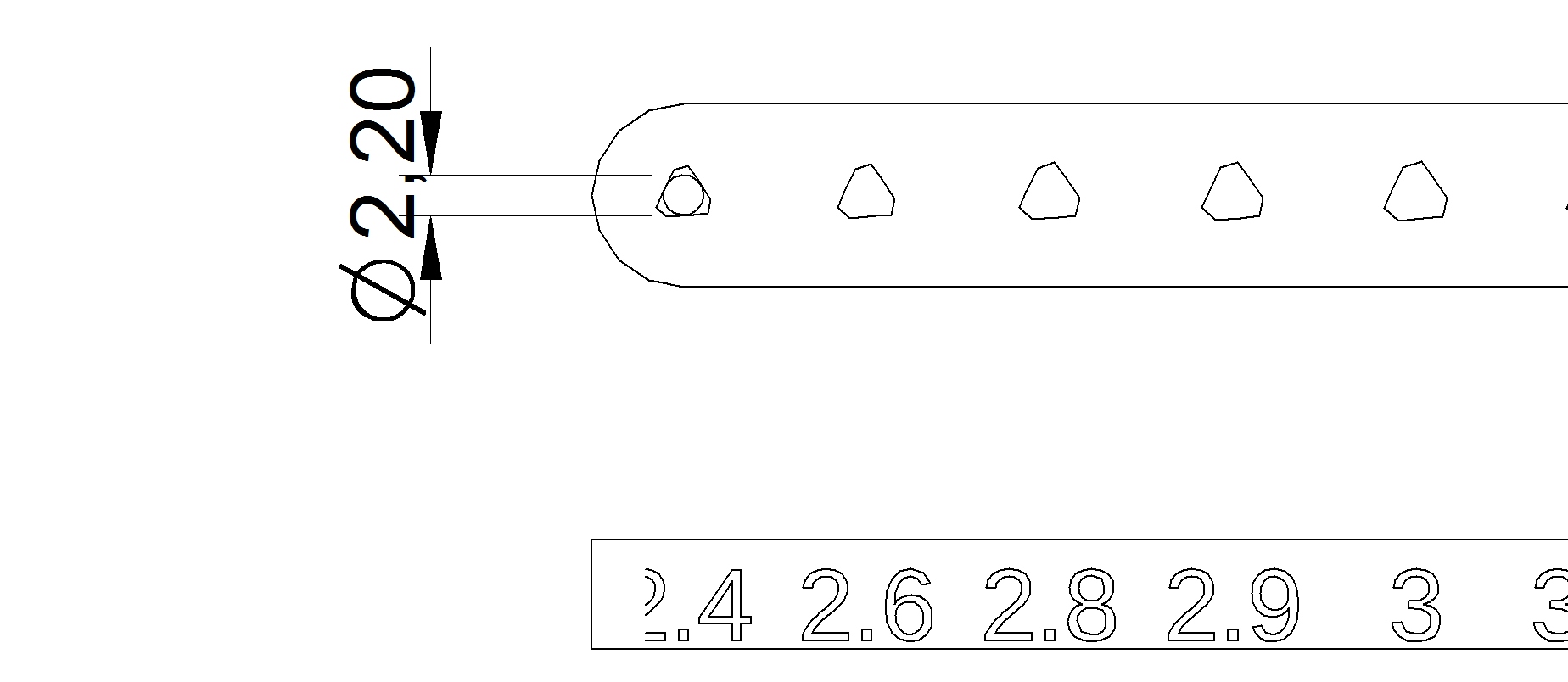
I have loaded the test piece into our CAD system (Siemens Solid Edge) and the holes appear to be quite faceted. Is this correct? It looks as if the cusp tolerance on the export is set a bit coarse.
I’m not sure what the engraved numbers refer to (clearly not the inscribed circle size!)
Is this right - do you want me to continue?
I’ve checked and we don’t have any import tolerance on stl import (so I don’t think it is down to me)
I need to talk to a colleague who knows more about the slicing software that 3D printers use. I know you can alter the skin thickness and infill percentage independently. This will affect the screw fit. I think most commercial cheap 3D printers use the same core open source software (even if they don’t bring the controls out to the GUI)
I am also a little confused, after some digging through the scad file and doing come calculations I have come to the conclusion that the inscribed diameter is: Max( 0.8*dn+0.4 , dn-0.4)
where dn is the nominal diameter on the side.
Thus we can translate the holes to internal diameters as so:
2.40 → 2.32
2.60 → 2.48
2.80 → 2.64
2.90 → 2.72
3.00 → 2.80
3.10 → 2.88
3.20 → 2.96
3.40 → 3.12
3.60 → 3.28
3.80 → 3.44
4.00 → 3.60
4.20 → 3.80
4.40 → 4.00
For an M3 screw the outer diameter before cutting the thread is 3 mm. The pitch is 0.5, therefore a perfect thread would have an equilateral triangle cut out of each side 0.5*sqrt(3)/2 ~ 0.433. By convention as you can’t cut the full triangular profile from a screw 100% tap is 3/4 of the calculated triangle. So for 100% tap you would normally drill 3- 2*.433*(3/4) = 2.35 mm
For plastic you normally cut a 75% thread (3- 2*.433*(3/4) *.75) = 2.5 mm
50% threads are common for steel and will still hold will reduced strength, for m3 this is (3- 2*.433*(3/4) *.75) = 2.68
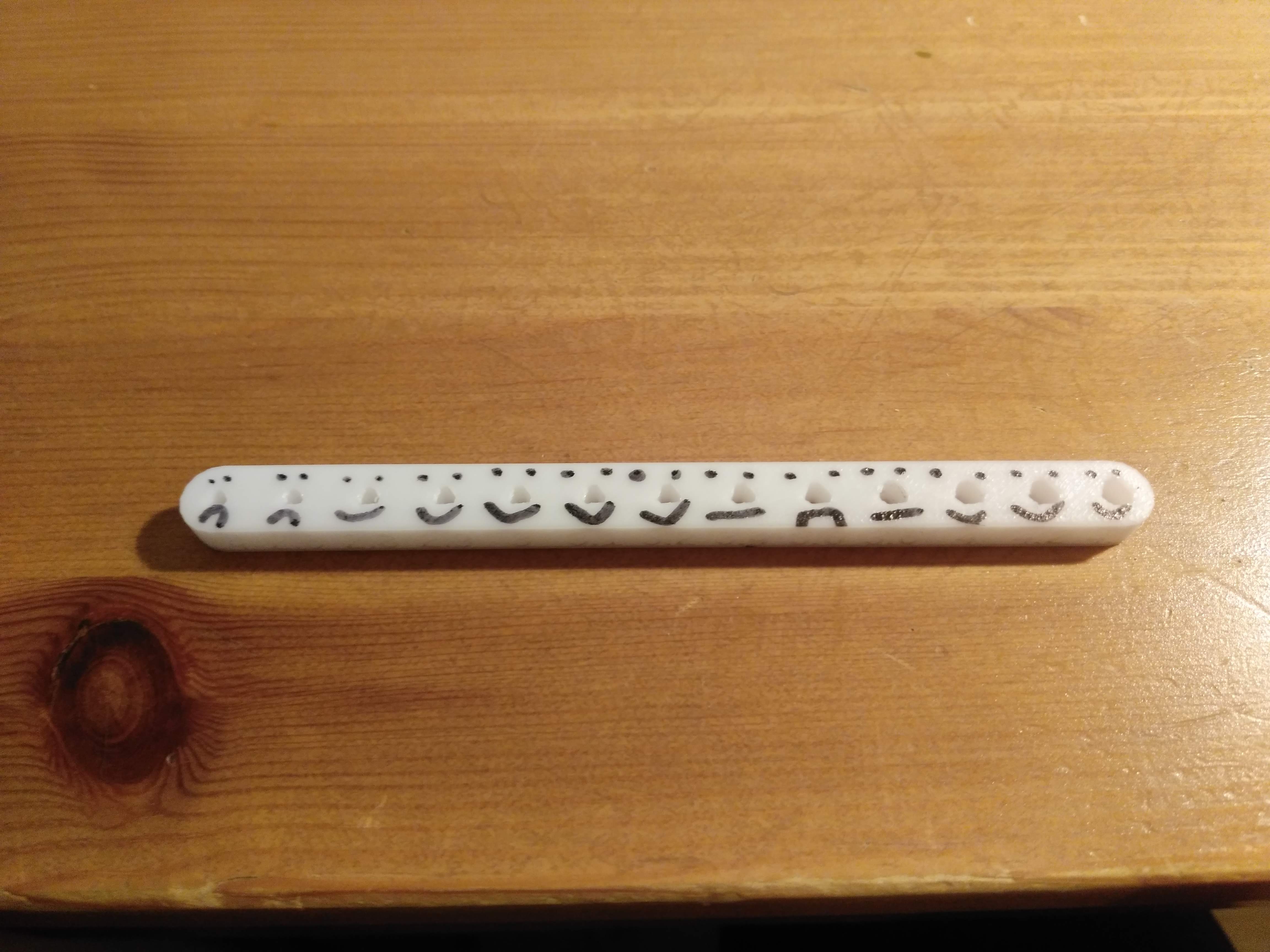
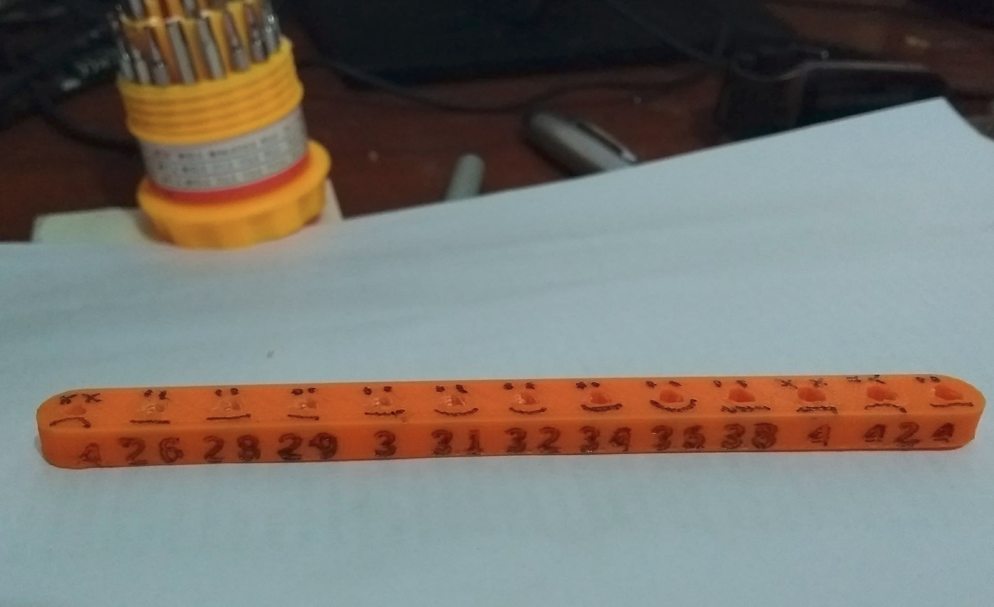
So from engineering I would believe holes with about 2.4-2.7 inscribed diameters would cut properly and hold. Based on Alex’s ( @vektor ) photo, the screws hold for holes with diameters 2.64 to 2.96, which implies that the holes are printing about .25mm smaller than they should be, which doesn’t sound unreasonable.
@rbowman It would make sense to me to change trylinder_selftap so that r is calculated as (nominal_d + splodge)/2
where splodge is changeable based on a test object, but using Alex as an example it should probably be estimated as about 0.25. If we do this then a hole with nominal_d of 2.5 should tap for M3 which is consistent with the rest of the world’s engineering.
Hi @clivec, the holes are deliberately a bit faceted, because the modeling software I use (OpenSCAD) tends to get slow when I use too many facets on the round parts, and I’ve noticed that putting too many vertices too close together can also result in bad G code for some printers. I thought I’d set it to have more facets than your line drawing shows, though, which probably means I forgot to specify a fragment angle, I should check that. I’m hoping that in the majority of cases it won’t make a big difference though, as it’s the flats that actually touch the screw.
In terms of what the numbers mean, these are the nominal screw diameter, which is then fed into a formula I dreamed up to generate the actual hole size. Said formula is defined in the OpenSCAD code and I should probably post it, but it’s very much just a guess! It rolls compensation for the printer and theoretical hole size for tapping into a single number, so possibly a more sophisticated test object would be useful…
yes, this absolutely does make sense - the formula you dug out is the missing link. I had intended the nominal_d to refer to the size of the screw rather than the size of the tapped hole, but it would indeed be nice to separate the calculation into a nominal part and a correction part. I’m still very much hoping that we can pick some parameters that work for most people without additional tweaking, because the triangular holes are a lot more tolerant than cylindrical ones - but it would be clearer to do the calculation for what the object should be, then tweak it based on measurements. At some point we should update the function based on the results of this little test, and share it in a more useful form
The issue with normal screws going into a cylindrical hole is they will try to form a thread rather than cut one which has very tight tolerance for working well.
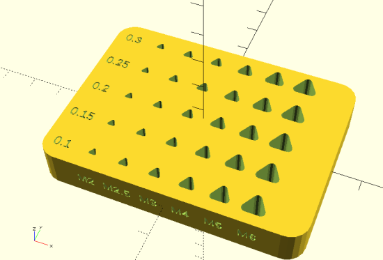
I have made a library which uses the calculations from above to calculate the required inner diameter for cutting a thread and then makes it bigger by a factor “splodge”. It has functions already calculated for M1, M1.2, M1.6, M2, M2.5, M3, M4, M5, M6, M8, M10, M12. Also for most smaller American UNC. There are also helper functions for calculating the tapping diameter for based on diameter and pitch, or based on UNC/UNF numbered or fractional sizes with specified TPI.
The library has a test object for M2, M2.5, M3, M4, M5 and M6 with 5 different splodge values (written on top):
I found our Prusa i3 was fine with splodge values of 1.5 - 2.5 for all screws, and .1 - .3 for M4 and above.
This object can be found in the Examples folder of the library, you can also right click this link and select “Save Link As” and save it as TapTest.stl. It is worth noting that 0.3 worked for M2-M3 but the screw easily broke the thread once fully in and continued turning.
If anyone has time to print this object too that would be wonderful. It is slightly more work tapping it, I did the M4 and above using a power drill once I got the holes started by hand.
Hi @rbowman
I have finally got around to printing the test object and putting some screws in (form submitted). I did find a difference in the build direction. I tried the object in two orientations; “numbers upward” and “holes upward”.
The screws were considerably easier to get in when the test object was built with “holes upwards”, so the edges of each layer ran through the numbered face. With “numbers upwards” the screws were more difficult to engage and seemed stiffer.
Discussing this with my colleagues we wondered whether you had tried using woodscrews rather than machine screws? The distance between core and crest on the woodscrew thread is much greater, so they would be much more tolerant of changes in pilot hole size. The taper on the tip will lead the screw into the hole, and (depending on the woodscrew type) the threadform is designed to cut or form a thread in a soft material. I will do some experiments to see if split tip (cutting) woodscrews or standard forming screws work better in 3D prints. Pull-out strength should be better than for M-form machine screws in this application. Woodscrews are also much more widely available than machine screws.
Hi @clivec, sorry to take so long to reply, something must have distracted me between seeing your post and responding to it… It was designed to print holes upwards, I’d probably use a different shape of hole to make it print nicely the other way up. @julianstirling and I have spent a little time thinking about woodscrews, but never quite made the jump. Part of our worry is that self-tapping screws can be a little harder to specify/obtain consistently (particularly in very small sizes, like M2.5 or M2 to mount the PCBs of the camera and Pi), whereas M3 cap head screws are usually a known quantity. Of course you can get woodscrews more or less everywhere, but my guess is that they’d be less likely to be exactly the same. If you have experience of sourcing/specifying that sort of thing, I’d be interested in how reliably you can get them a particular size. Whenever pull out force is really a worry, I try to just use a nut instead, but you are of course right, appropriate self-tapping screws would be stronger. Lastly, there is definitely an impression amongst some people (possibly including me) that cap head machine screws are what you use to assemble scientific instruments. While it’s not perhaps the most logical of reasons, I suspect that using machine screws helps the microscope to be accepted more readily, which is always a consideration.