OpenFlexure Microscope - epifluorescence acquisition

Rachel Aronoff recently raised an issue on the OFM software regarding fluorescence imaging. The thread has become far too general for the GitLab issue tracker, and so I’m making a copy here and moving the discussion.


Rachel Aronoff
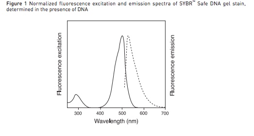
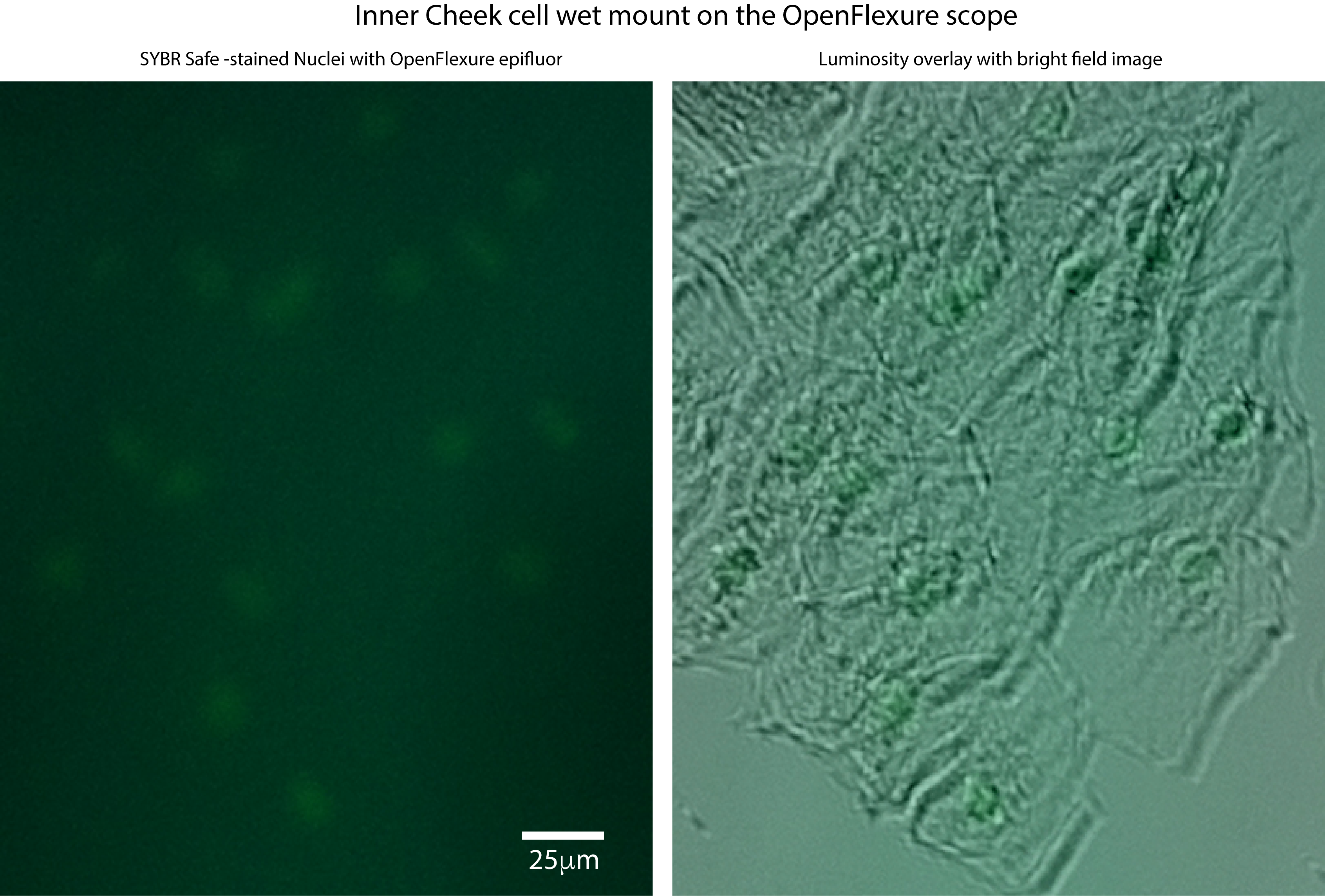
We would like to be able to image ‘sybr-safe’ -stained cells with the openflexure scope.
we have gotten the gfp filter set from comar, and can get images with bright fluorescein, but so far have not been able to see the stained DNA in cells. Even when fixed cells are bright enough to see on our ‘diy trans-illuminator’ (with side-illumination), they do not show up with the openflexure system so far.
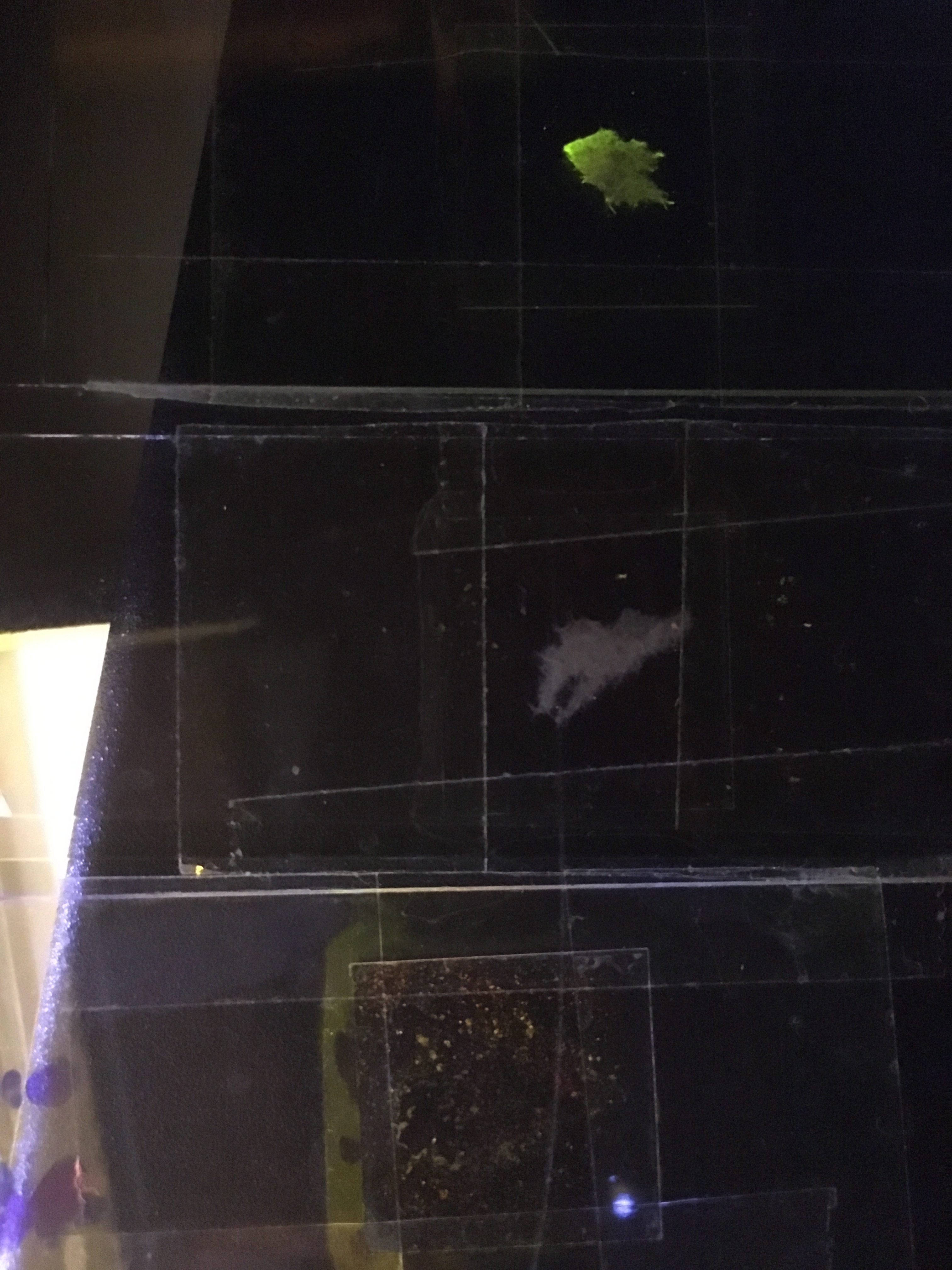
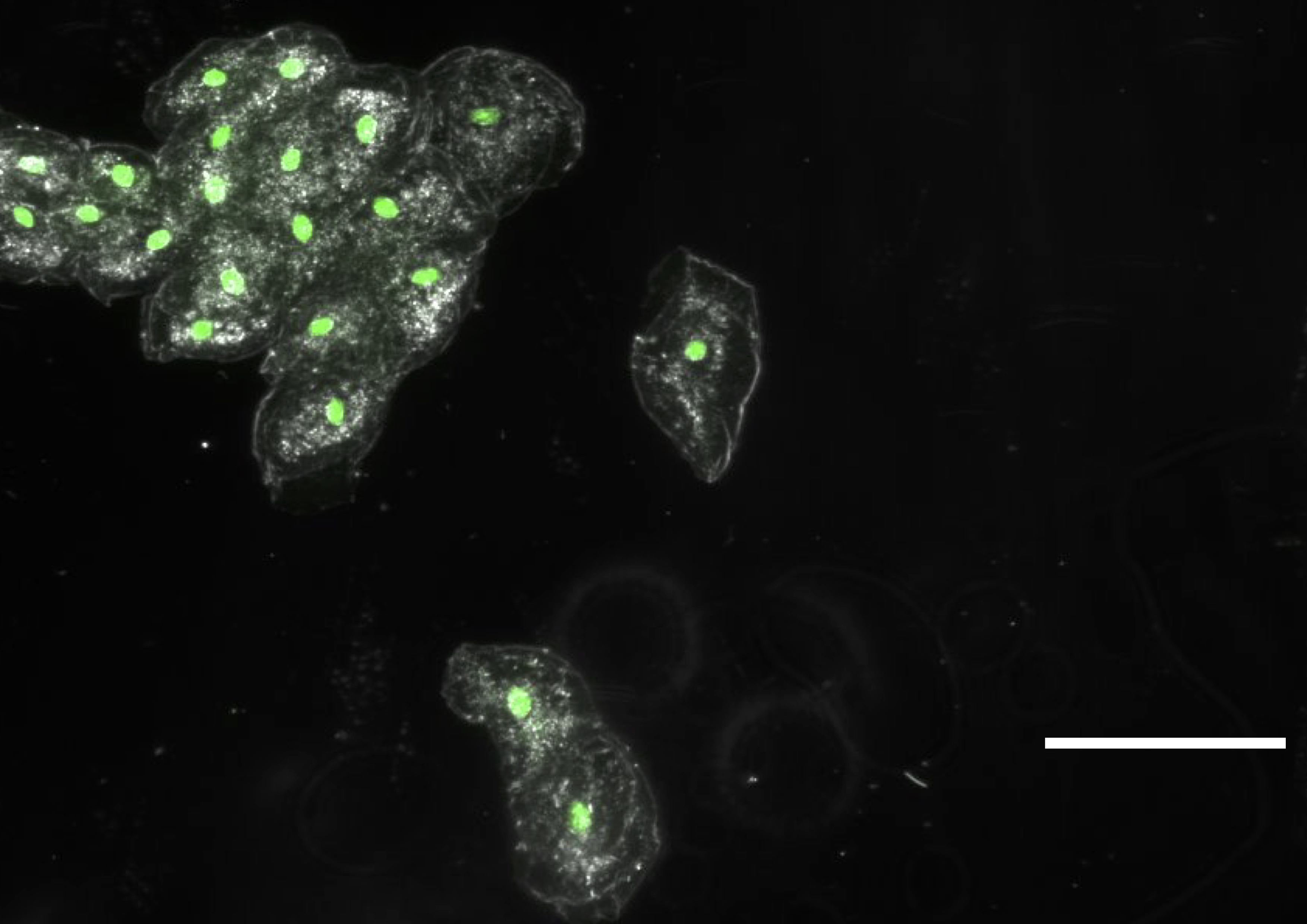
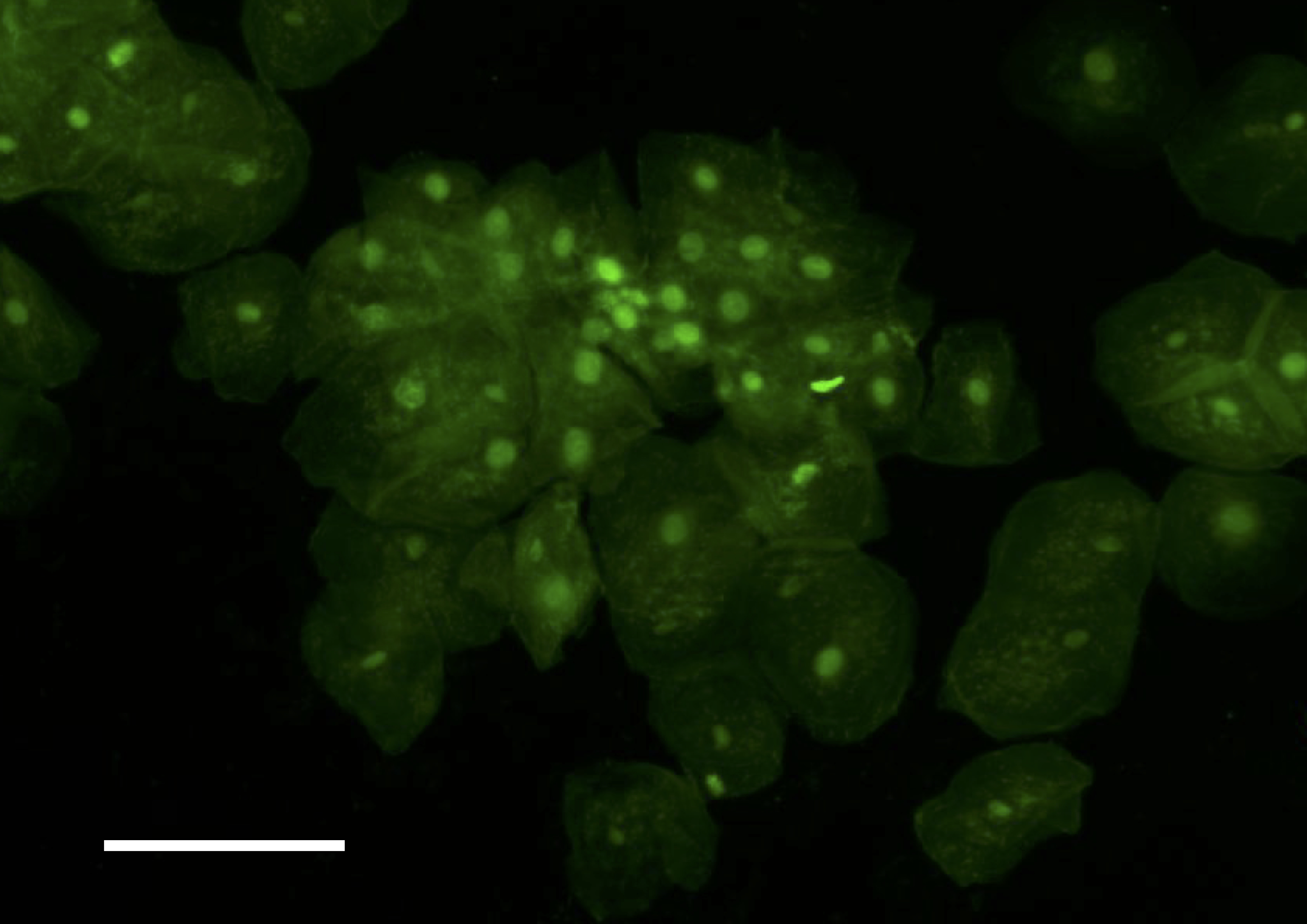
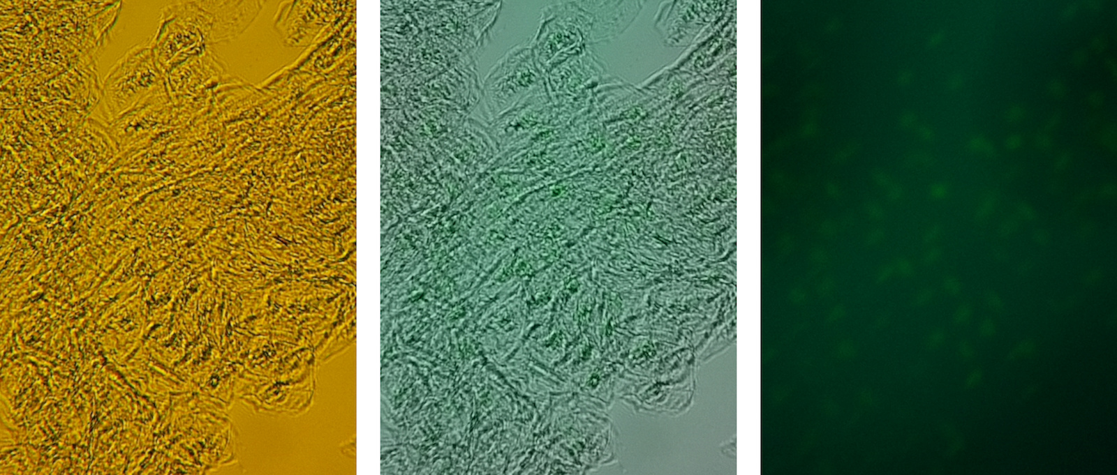
We are wondering if a sort of ‘binning’ could be tried, to average multiple images, thus reducing noise and increasing signal, in order to get the raspberry Pi camera to ‘see’ our stained cells. Can you get this to work, do you think? For your information, we have previously done such imaging with 500ms exposures on a standard lab epifluor setup and a 5x objective (when the bright field image is acquired with about 10ms exposures). I attach 4 pictures with the bright field and ‘epi’ images of cheek cells stained with sybr safe

https://gitlab.com/openflexure/openflexure-microscope-server/uploads/fd47dc3b9f1f382ac7b84ec7edc31259/2019-09-13_bfcellsmoresybr_arrows.jpeg

https://gitlab.com/openflexure/openflexure-microscope-server/uploads/3f7ffb4383538039d6f218f524e3f559/2019-09-13_epicellsmoresyb.jpg

, and of tissue, with fluorescein,

https://gitlab.com/openflexure/openflexure-microscope-server/uploads/ee0ac685a5fd913859d8b3eac1260752/2019-09-13_tissuefluorescein_epi.jpeg

https://gitlab.com/openflexure/openflexure-microscope-server/uploads/06275ac06d6e6da12e87e69f405c5bbb/2019-09-13_tissuefluorescein_bf.jpeg

picture with 3 samples, the top, with the cheek cells stained with sybr safe, the left, tissue in water, and right the very bright tissue with fluorescein.

https://gitlab.com/openflexure/openflexure-microscope-server/uploads/62196675de01f9fecfe9abbb57a04275/samples.JPG

Thank you for your input and help.

p.s.(We also still worry that our 10X fluotar objective or the blue LED we are using for excitation might need to be changed…)


Rachel Aronoff @rachelaronoff · 1 week ago

btw, I added the arrows to show where nuclei should be bright in the epi image (for just a few of the cells)


Rachel Aronoff @rachelaronoff · 4 days ago

@jtc42 (Hi, Joel, Richard says you are the one to ask! :slight_smile:
Do you have any ideas for us? As can be seen in the picture of the three slides through the ‘transilluminator’s’ orange filter, the fluorescein on the filter is super bright, but even that isn’t so impressive with the scope. Maybe we need to play more also with the camera calibration (any hints for that? - should it be done without a slide or with a non-fluor sample or with something fluor??), in addition to thinking about averaging images…? thx


Joel Collins @jtc42 · 4 days ago

The fact it’s so visibly bright in your photo but not so in the microscope images concerns me… Is there anything unusual in your filter setup that would explain that at all? Can you provide details on which filters you’re using, and how they’re set up in the microscope?

Regarding the camera calibration: While we’re still developing fluorescence imaging capabilities, we’re taking the approach of storing the raw bayer data in all our captures, and handling correction retroactively. This means we can test different calibration schemes without loss or re-taking data. For the time being, this is what I’d suggest.

We found that lowering the camera framerate, and using that to increase the exposure time helped a lot. Since the calibration is just a colour correction, I doubt you’d get any new information from that, only cleaner looking images. We had better results by increasing the exposure time massively. This will involve editing your ~/.openflexure/camera_settings.yaml file , as there is currently no option in the GUI to change framerate. It’s an easy change to make though. We got good results by setting it to 2fps, thus allowing a 500ms exposure. If you do this, make sure you have good vibration damping in place though!

Hopefully our work on fluorescence will continue in a week or so, and I’ll keep this thread updated if we make any developments.


Rachel Aronoff @rachelaronoff
· 3 days ago

Thanks.
Will try the 2fps edit this week!
Wondering if I can also get the default back for the calibration (just in case? worried as we did many different calibs with different slides in place, and blank).
We have the standard Comar filters for GFP,
1 550nm dichroic mirror, 25x16mm (GFP) Mfr: Comar; Part No. 550 1Y 116
1 490nm excitation filter, 25x16mm (GFP) Mfr: Comar; Part No. 495 1K 116
1 500nm emission filter, 25x16mm (GFP) Mfr: Comar; Part No. 515 1B 116
but I am concerned that one (the dichroic esp) might be upside down - if that is possible…
We still have not gotten the motor boards together - I should have gotten the one from Valerian, I think, not just relied on our lab member (who has a new job and got very busy) - but getting the fluor is more impt than the panoramas for the moment!
:slight_smile:


Rachel Aronoff @rachelaronoff · 2 days ago

ok, we got the framerate changed to 2 (used nano for edit, and saved the original camera setting yaml…), and maybe sensitivity is a bit better, with exposure set at 5000 the fluorescein/tissue is very bright. but still the cells were not satisfactory. I will try tomorrow with fresh cells… (Also, there may be a bug: I noticed that when I set exposure to 6000 it goes to 5983 -ms?- and if I change the gain, then say ‘apply settings’ it goes back to 1.0) do you think I should try flipping the dichroic or test another blue led?? thx!


Joel Collins @jtc42 · 2 days ago

Hi Rachel, glad it helped! Do keep us updated.

The exposure not quite matching is normal, and unfortunately is not something we can prevent. When you set the exposure, it sets a target exposure which the camera hardware will try to match. Often it settles at a value that’s just a bit off.

I’m not sure if the gain should behave in the same way. I’ll look into this. It may be a bug in the client doing some nasty rounding


Rachel Aronoff @rachelaronoff · 1 day ago

thx? and is the dichroic I got uni-directional? should I try to flip it?


Rachel Aronoff @rachelaronoff · 1 day ago

tried the flip, and it is odd - I expected a big effect, but the cells are still not satisfactory, and the tissue with fluorescein still shows up just fine. with the big files (14mb each) I made overlays in photoshop, however, and maybe there are a couple of possible traces of potential nuclei, post flip, but it is hard to be convinced. Should I try to send these overlays with WeTransfer to you? Maybe trying another LED is the next step?? Any word from your end? Also, I did a series of changing exposures, but I would still like to know what the units are for those numbers, esp as changing the frame rate should have made for 500ms exposures… What is the actual difference in exposure when I go from about 10k to about 20k, without changing gains, for a specific question. (for the cells, I did the bright field with 10k and the ‘epi’ with 20k most of the time today, but for the fluorescein 10k for both was perfect…) I would also like to understand more what the calibration does, but guess I will also try more of this tomorrow. Can you look into the idea of ‘binning’ multiple images, to reduce noise and increase signal? Are there other people out there using the epi successfully for cells already, who I could contact? Thanks again for your help!


Joel Collins @jtc42 · 7 hours ago

with the big files (14mb each) I made overlays in photoshop

Files that big sound like you’re storing the raw bayer data in your captures. Please be aware that photoshop is unable to read this data. It can be extracted using Python but it’s really a picamera-specific block of data.

Should I try to send these overlays with WeTransfer to you?

You’re more than welcome to, but I’m not sure what I’ll be able to add really.

Maybe trying another LED is the next step??

If you have some brighter LEDs that will likely help. We’re going to be exploring using LEDs that kick out ~2W of power once our PhD student has started again.

Any word from your end?

We’ve all been away or busy (or ill) recently, and our PhD student working on the fluorescence has been on a 2 week break. He’s due to return next week, but will have a week of induction activities. Once he’s settled in, I think we’ll start working on the fluorescence again.

Also, I did a series of changing exposures, but I would still like to know what the units are for those numbers, esp as changing the frame rate should have made for 500ms exposures…

The value is returned as an integer representing a number of microseconds.

https://picamera.readthedocs.io/en/release-1.10/api_camera.html#picamera.camera.PiCamera.exposure_speed

I would also like to understand more what the calibration does

We have a paper that should be released soon detailing what the calibration does. In the meantime, the file responsible for lens-shading functionality can be found here.

The routine is not super complicated, and the file has been heavily commented, so hopefully that’s useful.

Can you look into the idea of ‘binning’ multiple images, to reduce noise and increase signal?

This will almost certainly not appear in the microscope software, at least any time soon. We’re generally trying to keep data acquisition and data processing separate. What I might suggest we do is include a way to rapidly acquire a stack of images back-to-back without moving the stage. Then that stack of images can be overlaid in post.

Are there other people out there using the epi successfully for cells already, who I could contact?

As far as I’m aware, noone outside of the immediate project group is working on fluorescence imaging. @rwb27 might be able to confirm. At the moment, it’s heavily under development, so I consider this functionality very experimental.


Rachel Aronoff @rachelaronoff · 6 hours ago

well, PS did manage to open them for the overlays, although the exercise certainly did not clarify matters, and the final files were even more gigantic. Thank you for this further info, which I will look into further. I guess the question on the dichroic should also be addressed to Richard? (@rwb27)


Joel Collins @jtc42 · 5 hours ago

Sorry I should be clearer. The files contain a normal JPEG or TIFF (which PS can open and manipulate), but the majority of the data is additional raw bayer data that PS just discards. If the final files were also huge, that’s probably just down to whatever your PS export settings are set to.

RE the dichroic, Richard may have better advice than me, but if there’s absolutely no way to visually tell which side is which, then yeah maybe just trying both orientations is best. I’d be inclined to try and identify properly which way it should go though. The documentation may have useful information on that.


Richard Bowman :microscope: @rwb27 · 3 hours ago

I don’t think the dichroic should be particularly sensitive to which way round it goes. It’s probably best to have the coated side facing the microscope objective, but it won’t make a big difference. You can tell the coated side by holding it at 45 degrees and looking at the top edge of the optic - if you can see the edge clearly, you are probably not looking at it through the coated side of the dichroic.

Figuring out how to get the sensitivity up in fluorescence is definitely the hard part of all this. It’s good to see that you’ve got it working with GFP - but it’s odd that it looks so bright in your side-illuminated set-up and not in the microscope. If you side-illuminate the sample in the microscope, what do you see? I have had issues in the past with leakage of excitation light into the microscope doing that, so it’s not 100% trustworthy, but it might be worth a try.


Rachel Aronoff @rachelaronoff · just now

it worked not with GFP, but with the chemical fluorescein. that is why it is so very bright. how to get the sybr stained cell nuclei to show up is really the key thing that we need, for any of this to be worthwhile… yesterday’s fresh wet cells were no where near as bright as the ones shown above (dry and with tons of sybr)… will try adding a side illumination. hmmm. (and double check the dichroic coating) so you concur that the calibration is not so helpful?? I wonder if a previous calibration done is messing up the acquisition now, and am sad that averaging images does not seem readily feasible…


Joel Collins @jtc42 · just now

Hi all,

I think this thread would be better suited to the GOSH forum at this point. It’s become far too general to using the microscope, where this is an issue tracker for the server-side part of the microscope software specifically.

I’m going to create a GOSH thread on this, and once that’s online, I’ll close and lock this issue so we can move general discussion there.

and am sad that averaging images does not seem readily feasible…

If this is something you’re particularly interested in, could you please raise a specific issue about this? That way, we can assign the feature to a release and it might get included at some point. It’s important to state that because of the way our camera streams work, it’s not trivial to add, so a separate issue would be ideal.

I think Joel’s statement that averaging images isn’t feasible is perhaps a bit more specific than it seems - averaging images absolutely can be done, but it might be hard to do it in the live video stream in eV. It would absolutely be possible to put this into eV, but it would (as Joel says) not be a trivial amount of work, and ultimately it’s not currently something that the project that pays for his time needs, so he’s not able to make it a priority.

We do still have a student (Joe) working to get decent fluorescence imaging working, including figuring out how sensitive we can get it.

As a last suggestion to Rachel, when you have it set up on the microscope, are you able to see the blue light coming out the objective, and observe the green fluorescence by eye, as it seems you can do with the slide/illumination combination in your photograph?

Have you tried adjusting the position of the LED where it joins the beamsplitter cube, and indeed tweaking the beamsplitter cube? One of the bits of this system that most needs overhauling is the mounting for all the fluorescence optics - if you don’t align them very carefully, you can end up illuminating the wrong bit of the sample, which will massively hurt your sensitivity.

Lastly, are you using the fluorescence parts from the master branch, or the newer version with the lens in? The latter is barely tested and not documented, but we are hoping to fix at least one of those two problems in the next month or so.

I just chatted briefly to one of my biological collaborators about sybr-safe, and she mentioned it was way brighter under UV light. Are you sure 460-470nm is the right wavelength? The filter set described in that thread was for GFP/fluorescein, but perhaps you actually need a UV LED (and corresponding filters). You might get away with a UV LED and the existing filters, but perhaps you should remove the excitation filter, that might be attenuating the light. Have you checked the spectra of the filters and the dye? Sorry if that’s an obvious question, but sometimes obvious questions are worth asking! Posting/linking to the relevant spectra here would be helpful for anyone else reproducing what you are doing.

1 Like

You could also try lowering the framerate further to allow even longer integration times. If your microscope is properly vibrationally isolated, it should be more or less equivalent. I appreciate this is only a pit-stop solution, but given our current roadmap, averaging may well not be included for a while yet.

Let us know how it goes!

Indeed the sybr-safe is especially used for gel band staining as an alternative to EtBr, and would be brighter with UV light, as officially its excitation max peaks are at 280 and 502nm when bound to DNA. However, most lab transilluminators are at about 365nm to see bands in gels, and that works fine for sybr-safe stained gels too. For our cheek cell comet assays, however, we were always very successful imaging (on a lab scope) with the GFP filter set, so that’s what I thought would be best to try in this OpenFlexure context. I also had some concern in our open public lab that the UV might pose more hasards for users… I tried the 3W blue LED yesterday without the excitation filter, and that again was not satisfactory for the stained cells, though brighter… Btw we have modified the LED holder so I can hopefully fit various options better, and may also try an LED with a UV peak today… (Clearly, from the slides I imaged with our DIY transilluminator, using blue LEDs, the sybr cells look more yellow than the fluorescein, confirming that going for green isn’t ideal. Probably I could also look into getting another filter set for a more yellow emission.) Thanks for your help, again!

I understand, Joel… Our OpenFlexure build is not on an air-table, however - I doubt it would be considered ‘properly vibrationally isolated’ at all. So, already the 500ms integration time is probably quite a lot for these conditions. Also, if I try to change the frame rate right down to 1 (one frame per second), won’t all my ‘bright field’ images with the white LED on top be quite overexposed?? Thanks for your feedback, and help.

just to show yesterday’s slides under the transilluminator: fluorescein on tissue is above, water on tissue in middle, and cells with a lot of Sybr-safe (more yellow than fluorescein) below…

and here is the official word on excitation emission from thermo fisher for sybr-safe bound to DNA
thermofisher

If you want good vibration isolation on the cheap:
Get an inner-tube for a bike tyre and pump it about 3/4 full. Then get a concrete paving slab and put it on top. Put the microscope on this.

In general you want something squishy that reacts slowly, with something that cannot store vibrations on top. To test if something stores vibrations just clunk it with something metal. If it goes “diiiiiiiiiiiiiiinnnnnnnng” like a bell or a gong it is bad, if it goes “thudk” it is good.

3 Likes

If you are trying to use the same exposure time for bright-field and fluorescence imaging, you will always either overexpose the bright field images, or get really dim fluorescence images. You will definitely need very different camera settings for the two imaging modes.

1 Like

yes, I have been doubling and tripling exposure times for the fluorescence vs the ‘bright-field’ acquisitions. (i.e. 5k for bf and 15k for blue led) As it is still surprising how weak the fluorescein image comes out, my hoping for the cells to show up may be too over-ambitious.
when I tried merging 5 identical images of the cells yesterday, the nuclei certainly did not pop out for me… :frowning:

to go back to the choice of gfp filter cube, I think it is pretty clear from the manufacturer’s data (in addition to our previous experience on lab epi-fluor rigs) that the sybr-safe should be excited (when bound to DNA) well by 460-470nm blue led (that can also have a hidden uv component) for emission of green light… sigh

two more points have come out today. 1) I put a 150 ohm resistor on the 3W blue LED, and am just running it from the 5V pins on the raspberry pi. Maybe I need a separate power supply (and much smaller resistor) to get any extra excitation with this led? and 2) averaging 5 images isn’t likely to be enough to make a big difference (noise will reduce by the square root of the number of replicates)…

just something more to mention (3oct controls):
Now I know all my samples were just fine, for imaging on a standard lab scope (Zeiss Axioscope at UNIL DMF).
I will attach a sample image from one of yesterday’s wet mount slides… (all worked well in today’s controls…)


And here is one of the dry cells stained with sybr-safe:

  • the white lines in both these images is the 100micrometer scale bar.

Not sure if I will be able to get this ‘diy’ setup to work for fluorescence of the stained cells… :frowning:
The filter cube should be good as it sees the fluorescein signal, but I guess it is a problem of the camera sensitivity to see the stained nuclei… Am still trying more LED tests (funnily, for smaller resistance, it is a much bigger beast! =)

For (1) I think it would be well worth consulting the LED’s datasheet. If you are using a 150 ohm resistor, with a 5v supply, and a typical blue LED (which has a junction voltage of somewhere in the region of 3.5V, that means you’ve got 1.5v (supply voltage - LED junction voltage) dropped over 150 ohms, so your current is about 10 mA. That means you’re really running it at something like 35 mW (power=volts x current=3.5V x 10mA), not 3W, i.e. 1% of it’s rated power.

Do not try to run a high-power LED off the Pi GPIO pins - at best it won’t work and you’ll blow a polyfuse. At worst you will completely and permanently destroy your Pi.

With a separate power supply, you can calculate the resistor you’ll need, based on the input voltage, LED voltage, and LED current requirements. That sets the voltage and current through the resistor, and you can use Ohm’s law to figure out the right resistance. That said, a constant-current driver is usually a much better way to drive big LEDs like this. We have not designed and documented one, we might do in a few months’ time and rest assured we will post about it when we do.

There are plenty people who have made constant-current circuits for LEDs though, e.g.:

1 Like

I have been doing a bunch of tests with an external power supply, the ‘diffused’ LED hooked to the same ‘power resistor’ as used before (4.7 ohms) and could get the blue LED as high as 9.65V (1Amp). bright! (5V gives about 300mA current for a more reasonable level to not fully saturate the camera. 7V gives about 600mA.)
Thanks for your further info above, Richard! (confirming also what we now have seen empirically too)
However, epifluor from the sybr-stained cells is still not convincing, although I did two exposure and voltage series today, that with a bit of adjustment (fingers crossed) might get the nuclei to ‘pop out’ if I am at all lucky.
I had also worried that the RPi camera simply isn’t able to pick out the signal due to resolution issues, but I got images of a hemocytometer grid and did the calculations- we get 2 pixels per micrometer with the RaspberryPi camera at full resolution, which is not so far off from the lab system with 10x objective… The nuclei of these 50um dia cheek cells are probably only about 10um in diameter (max) of course, so maybe the this is still the problem. sigh. The other worry is that the ccd camera in the lab is simply way more sensitive, and that that is what is needed to see what we need to see… More soon, I hope!

Note added 13oct: (I need some response to this thread to say anything more in a new post! is anyone seeing this? :slight_smile:)
it is clear the filter set is the main problem.

Those Comar ones I ordered are not correct.

1 550nm dichroic mirror, 25x16mm (GFP) Mfr: Comar; Part No. 550 1Y 116
1 490nm excitation filter, 25x16mm (GFP) Mfr: Comar; Part No. 495 1K 116
1 500nm emission filter, 25x16mm (GFP) Mfr: Comar; Part No. 515 1B 116

I should not have followed the recommendation in the issue thread, I guess…

When these ‘excitation and emission’ ones are put together, and I look at a normal fluor bulb’s light, turquoise blue comes through.

I have to find the correct band-pass filters (that hopefully won’t be too expensive).
Anyone have a good idea about this?
ciao for now

Joel just checked the ones we are currently using (which may or may not match the ones I used in the past), and the excitation and dichroic are the same as yours, but the emission filter we have is a 510 IY. He also reckons it’s not impossible that there is a little leakage, and that we’re relying on the dichroic to cut that down.

I’ve never tried fluorescence imaging with a 10x objective; note that the difference between cheap and expensive 10x lenses in terms of Numerical Aperture is a lot bigger than at higher magnifications. That means a posh 10x will get a lot more fluorescence signal than a cheap one. I’m sure the Pi Camera is not as sensitive as it could be (the bayer filter is a pain) but your objective lens may not be helping. I’d not realised you were working at such low magnificiation…

Thank you for your further investigations!
When you hold the 510 IY next to the 495 IK and look at a light - what do you see? how much light, if any (and what color, if so?) comes through??
This may indeed help. (I just went to the first OpenFlexure epifluor issue thread - where I got my Comar order numbers - to try to note all this also… please see: https://gitlab.com/openflexure/openflexure-microscope/issues/43#note_237046645)

I also just looked again on the Comar site, and the transmission of the 515 1B filter looks much narrower than desired - green/green yellow is being cut out (so that also explains the fluorescein not being so bright) - also vs. the 511 1B possibility) but the 510 1Y definitely looks better - as it lets all light longer than 500 through!

So, I will just await your answer on the combination of the two (what is seen)! thx

In terms of our 10x objective - it’s a good one, I think - Fluotar … (I can take a picture again for you, if you like) - and with just 4x or 5x objectives we see our comets well, ordinarily (on the lab scope with ccd). Of course, as the max resolution of the Rpi Cam was calc’d to be about 2pixels per micrometer (using an image of a hemocytometer grid at full res), we are indeed talking about just a few pixels per nuclei in the intact cells. So, a more powerful objective does indeed seem likely to help… (should be ok -even if more images will be required to take the full ‘panorama’ of our samples…)

I’ll leave checking the filters in the lab to Joe or Joel, but to answer your point about 2 pixels per nucleus, remember it’s a colour camera with a Bayer filter. That means only every other pixel is sensitive to green light. I’d recommend increasing your magnification - if you’re picking up something that’s only a couple of pixels wide, and it’s centred on a red or blue pixel, you will really struggle to see it.

1 Like

Today’s update:
I am very glad to have already printed the reflection illuminator set, and started on the main body with the extra room for it to insert readily! Luckily, went ahead and ordered the long pass filter from Comar, even without your verdict on the combination test (exc and emission filters together should not let pass blue light), since apparently the co is not going to keep single items in stock any longer… whew, for me, for the moment, but - more sourcing should be done…

Also, to clarify the size/pixel issue - the inner cheek cells are about 50microns in diameter, so the nuclei are about 5-10micron in the fixed preps, a bit smaller in wet mounts… Not only are there more than 2 pixels per nucleus (maybe up to 20), but in fact with the 10x lab scope we only had 0.645microns/pixel, while the full res RpiCam gives 0.5microns/pixel, not so very much different.
Your point regarding the Bayer filter is well taken, however, esp in comparison to the lab rig CCD. Perhaps this is another reason to avoid red fluor in particular with the RpiCam, since at least there are 50% of pixels that are green ! :wink:
Thanks again for the feedback!

the new long pass filter indeed made a difference!
got my first images that show the nuclei of sybr-safe stained nuclei, still with the 10x objective! see also…

and here’s one more example from the center of the images…
croppedsybrnuclei2smaller|690x293

and one more from today!


Hoping it will be even better in version 6 of the OpenFlexure, with the different reflector insertion rig…