Replicator team- Mothbox DIY

Hi everyone,

My name is Ali, and I am part of the Replicator Team at the University of Washington. We are currently working on replicating the Mothbox DIY open hardware project and documenting our experience so it can be useful for other builders. The Mothbox DIY build process is already documented clearly in the link below. My goal here is to review the documentation from a replicator’s perspective and identify any areas that could be clarified or improved.

Main Mothbox DIY build documentation:
https://digital-naturalism-laboratories.github.io/Mothbox/docs/building/mothbox_diy

Cut parts page:
https://digital-naturalism-laboratories.github.io/Mothbox/docs/building/mothbox_diy/cutparts/

While going through the build process, we noticed a few places where additional details could make the documentation easier to follow, especially for new replicators or people who may not be familiar with laser cutting, GitHub, or some of the materials used in the build.

General documentation clarity

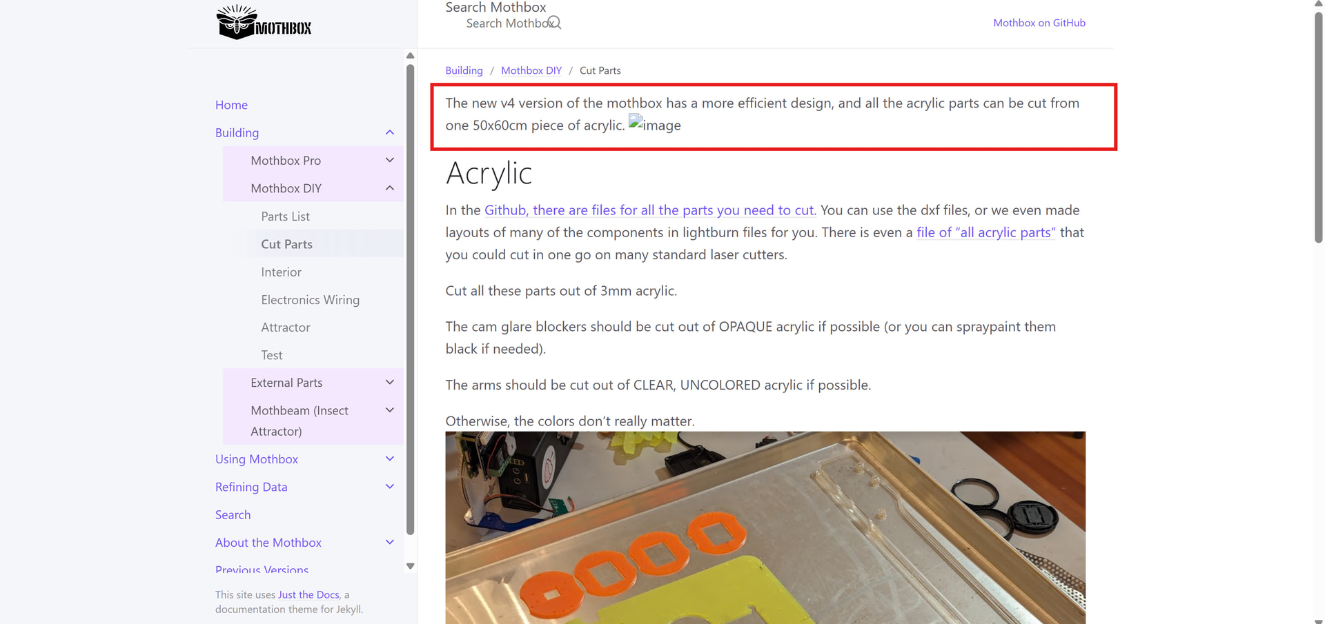
On the cut parts page, it looks like one of the images is missing. Since this section is important for understanding the laser-cut components, restoring or replacing the image would make the instructions much easier to follow.
Another area that could use clarification is the mention of “felt.” A close-up image, along with a short explanation of its purpose and possible substitute materials, would be very helpful. There is currently a picture, but we were still unsure how the felt helps or how it should be installed.

Laser-cut parts and materials

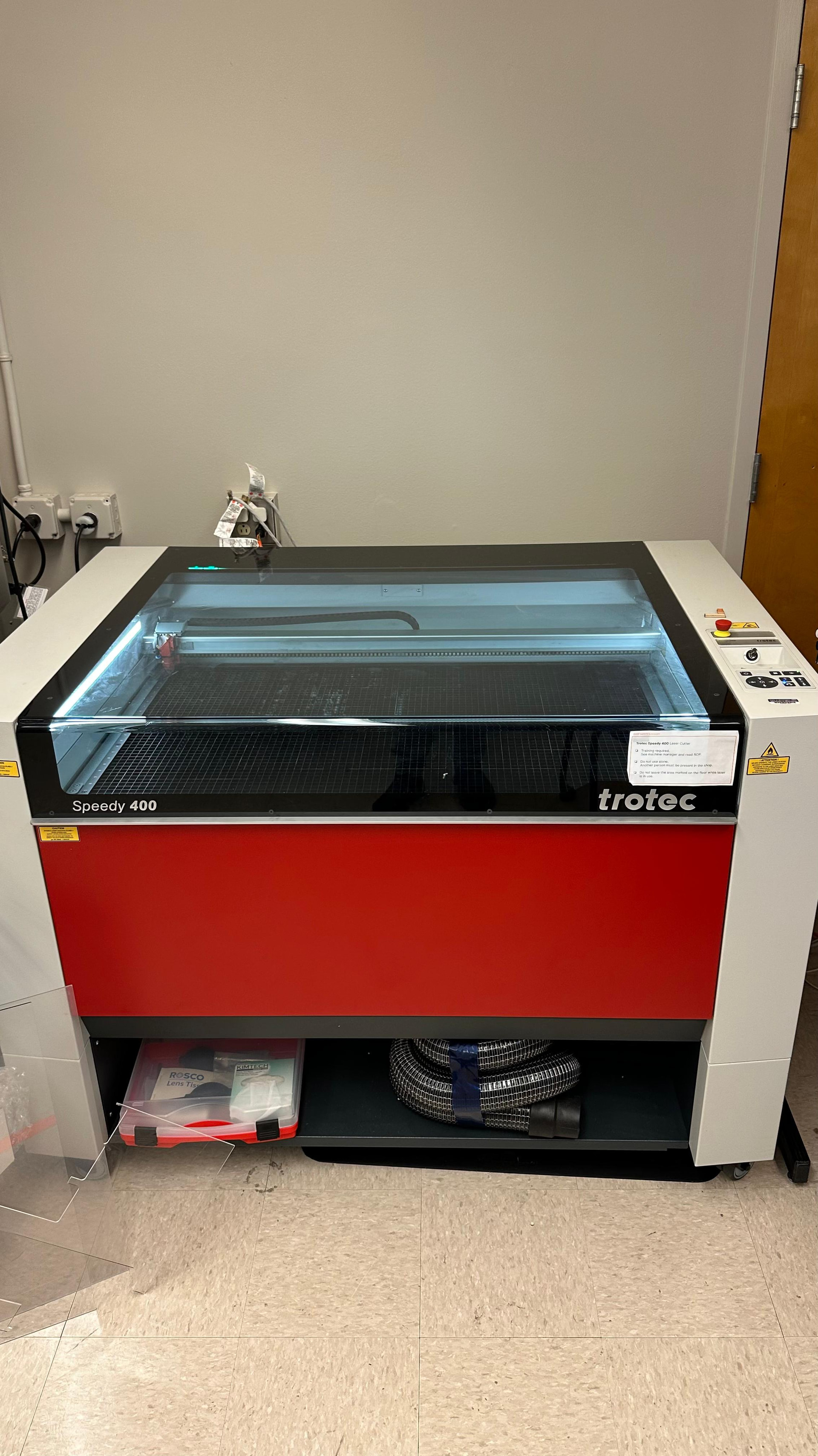
The laser-cut parts were one of the more difficult parts of the build for us to interpret. A labeled photo showing all cut parts laid out together would make a big difference. It would be especially helpful if the photo included the name of each part, how many of each are needed, and which pieces should be cut from clear acrylic versus dark or opaque acrylic.
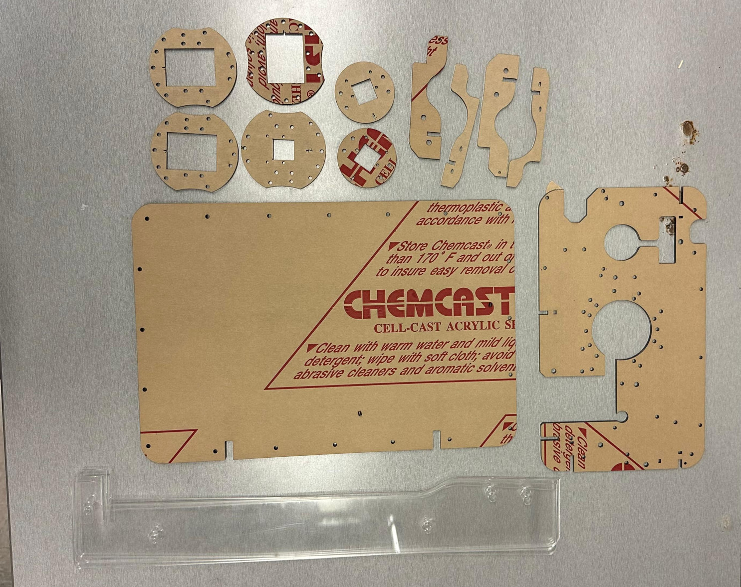
For example, we understood from the documentation that the legs need to be clear, but it was not immediately obvious which pieces were the legs. Having a labeled image would help future builders avoid confusion.

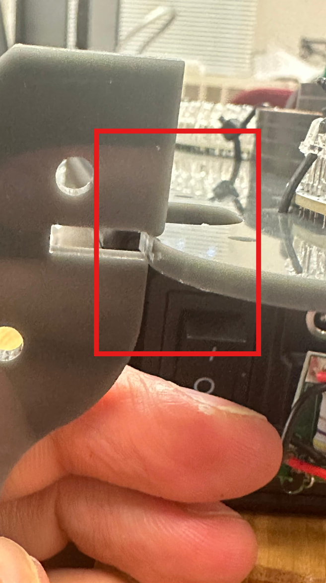
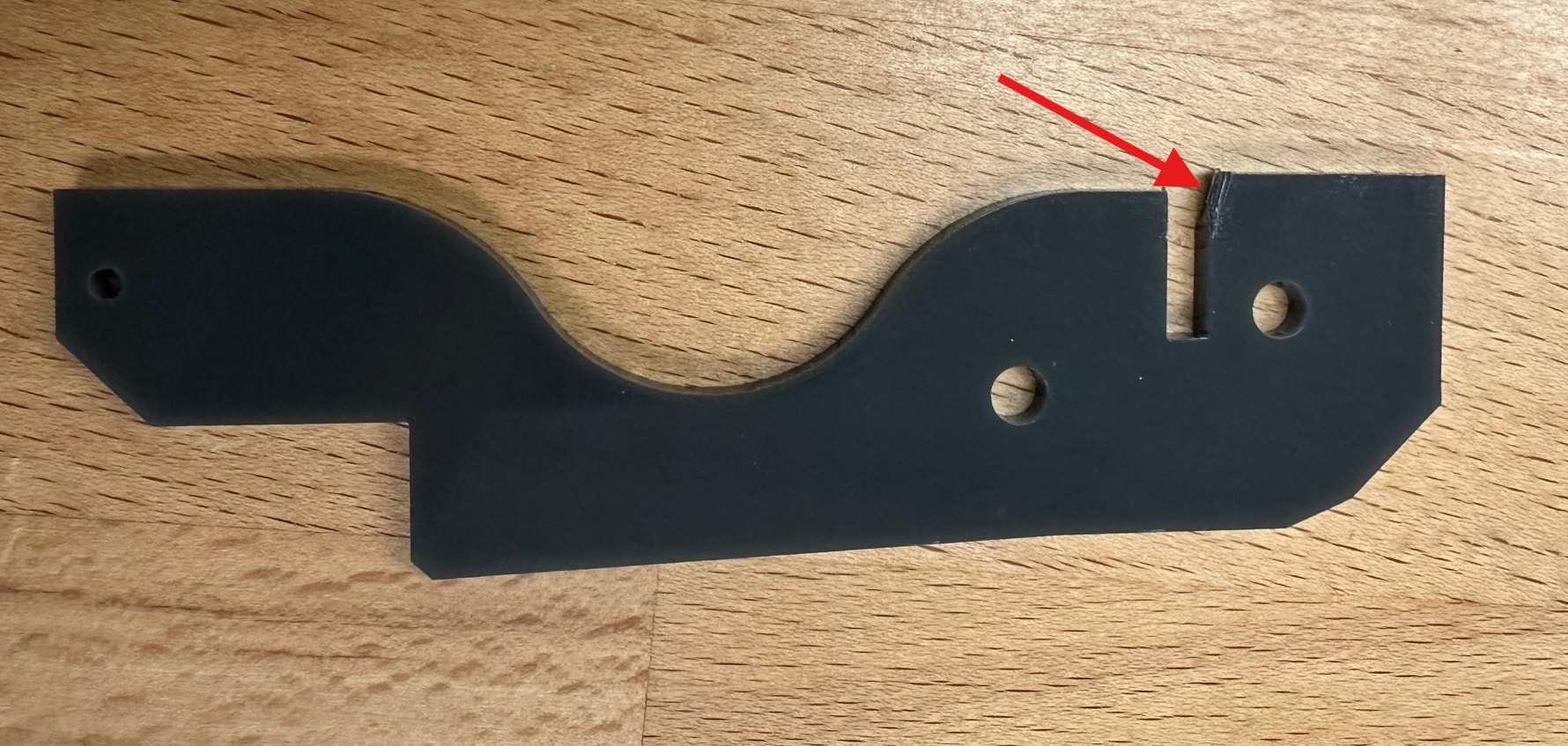
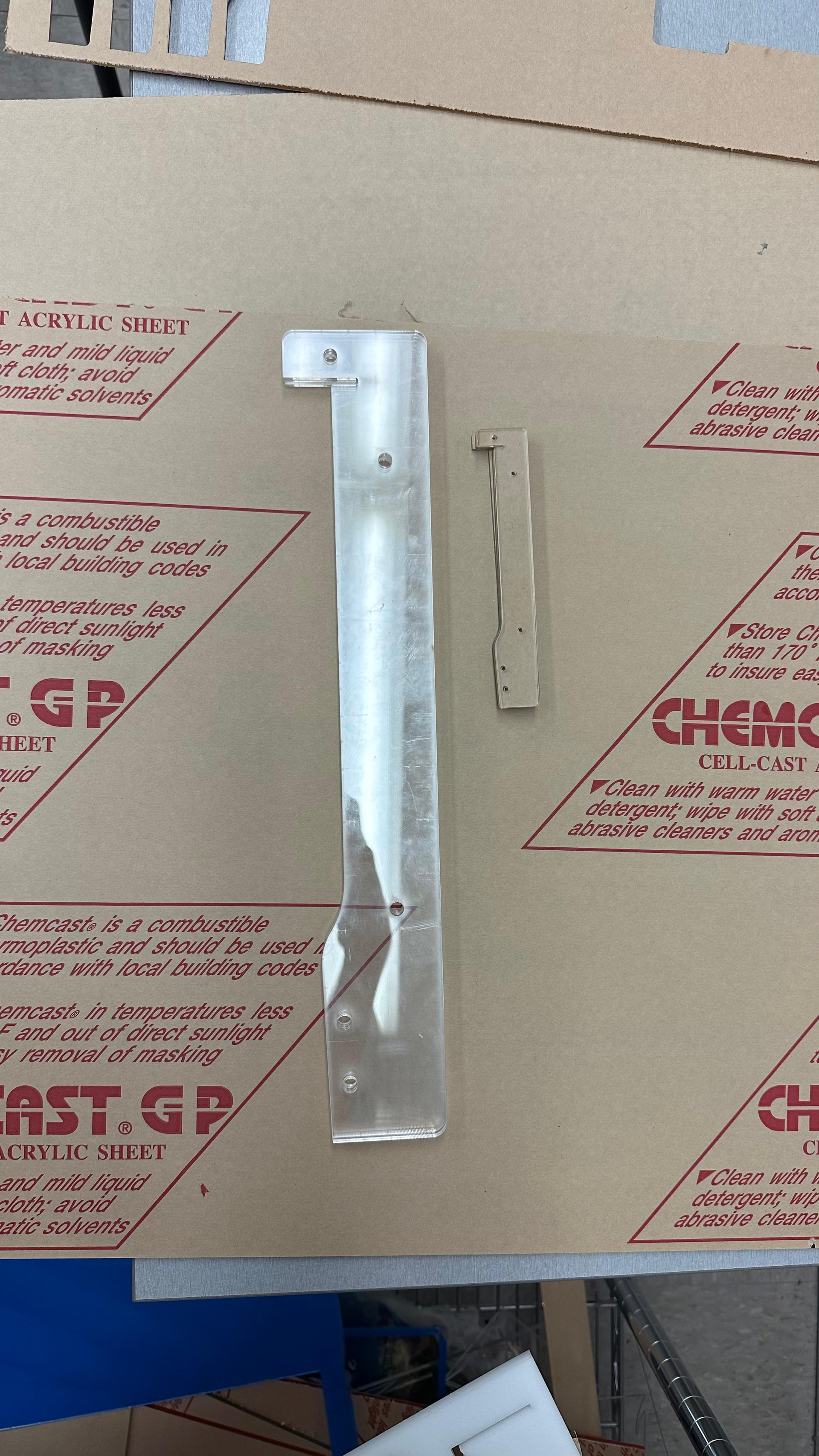
It would also be helpful to include dimensions for the different laser-cut parts. After cutting the legs, we were not sure whether the size was correct (see the picture below). Because no dimensions were listed, we had to spend extra time checking and guessing. Including basic dimensions would allow builders to confirm that the files were scaled correctly and that the cut parts came out accurately.
We also had some trouble with the acrylic sheet we used, which did not cut very well. More specific recommendations for acrylic type, thickness, and whether cast or extruded acrylic is preferred would help reduce failed cuts and wasted material.

GitHub files and laser cutter compatibility

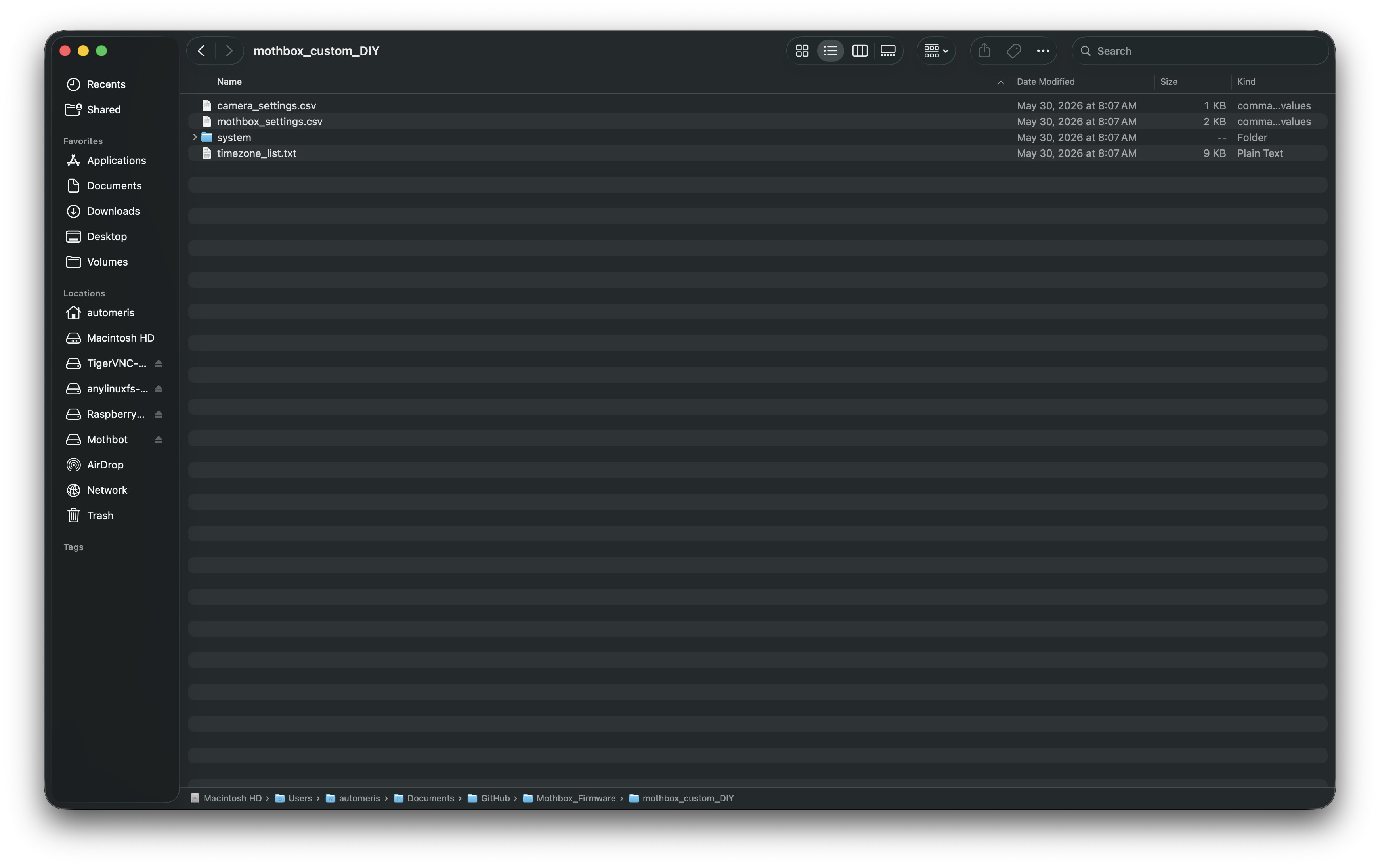
When we clicked the GitHub link, we found the files for the parts that need to be laser cut, but there seemed to be two versions. It would be helpful to explain the difference between these versions and clarify which one should be used for a standard build, or whether either version is acceptable.
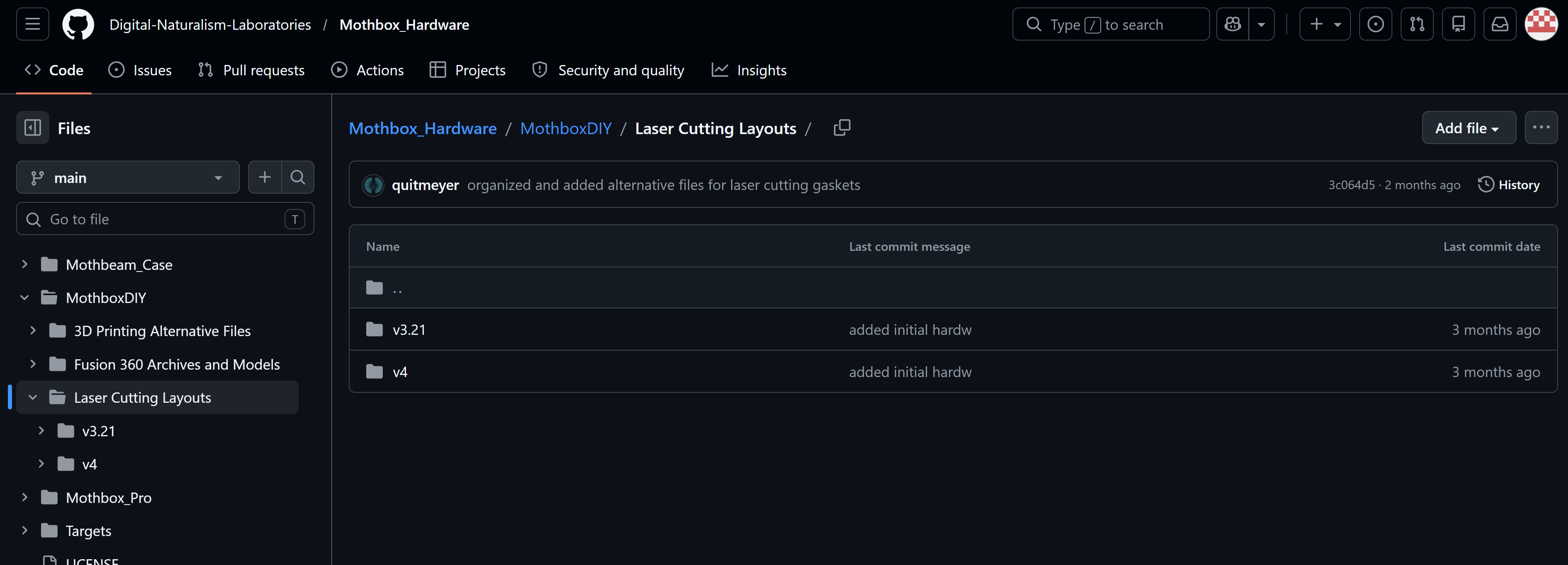
The available LightBurn file may work well for many laser cutters, but our lab uses a Trotec laser cutter with JobControl software. JobControl cannot directly open .lbrn2 files, which are native to LightBurn. For JobControl, the design would need to be exported from LightBurn as PDF, DXF, or SVG. Including these additional file formats in the documentation would make the project more accessible for people using different laser cutter software.
Also, for builders who are not familiar with GitHub, downloading the files may not be obvious. A short note explaining how to download the full repository as a ZIP file, or how to download the needed cut files, would be useful for beginners.

Ordering electronics

One additional note for future builders: we ordered the Raspberry Pi-related component about a month ago and still have not received it. Based on our experience, I recommend ordering the Raspberry Pi and related electronics as early as possible, since shipping or availability delays can slow down the build.

Overall, the Mothbox is a very interesting project, and we are excited to continue working on it. These suggestions are based on our replication experience so far, and I hope they help make the build process smoother and more accessible for future replicators. Stay tuned — more updates are coming as we continue the build.
1 Like

Hardware Assembly Report: Camera Glare Blocker, Ring Light Disassembly, and Mainboard Assembly

The goal of this assembly was to prepare the camera lens glare blocker, disassemble two ring lights, reuse the lamp assemblies, mount them to the mainboard, and prepare the board for adding the camera and Raspberry Pi.


1. Assembling the Camera Lens Glare Blocker

Before working on the ring lights and mainboard, assemble the camera lens glare blocker.

For this step, I followed the main tutorial instructions for the Mothbox interior assembly. The basic idea is to take the six laser-cut circles and stack them on top of each other to form the glare blocker.
https://digital-naturalism-laboratories.github.io/Mothbox/docs/building/mothbox_diy/interior/

Take the six circular laser-cut pieces and stack them together in the correct order. Make sure the holes and cutouts are aligned before securing them.

Once the circles are stacked, check that the camera lens can fit through the center opening. The stacked circles should form a small tunnel around the lens. This helps reduce glare from the ring lights and keeps unwanted light from entering the camera view.

Camera Cover Issue

One issue I found was that the camera may come inside a cover or protective housing. The original documentation did not mention this clearly.

If the camera is still inside its cover, it may not fit into the laser-cut glare blocker parts. To fix this, remove the screws from the camera cover and take the camera out of the housing. After removing the cover, the camera should fit properly into the laser-cut parts.


2. Disassembling the Ring Lights

The next step was to open the ring lights so the internal lamp parts and electronics could be removed and reused.
Procedure

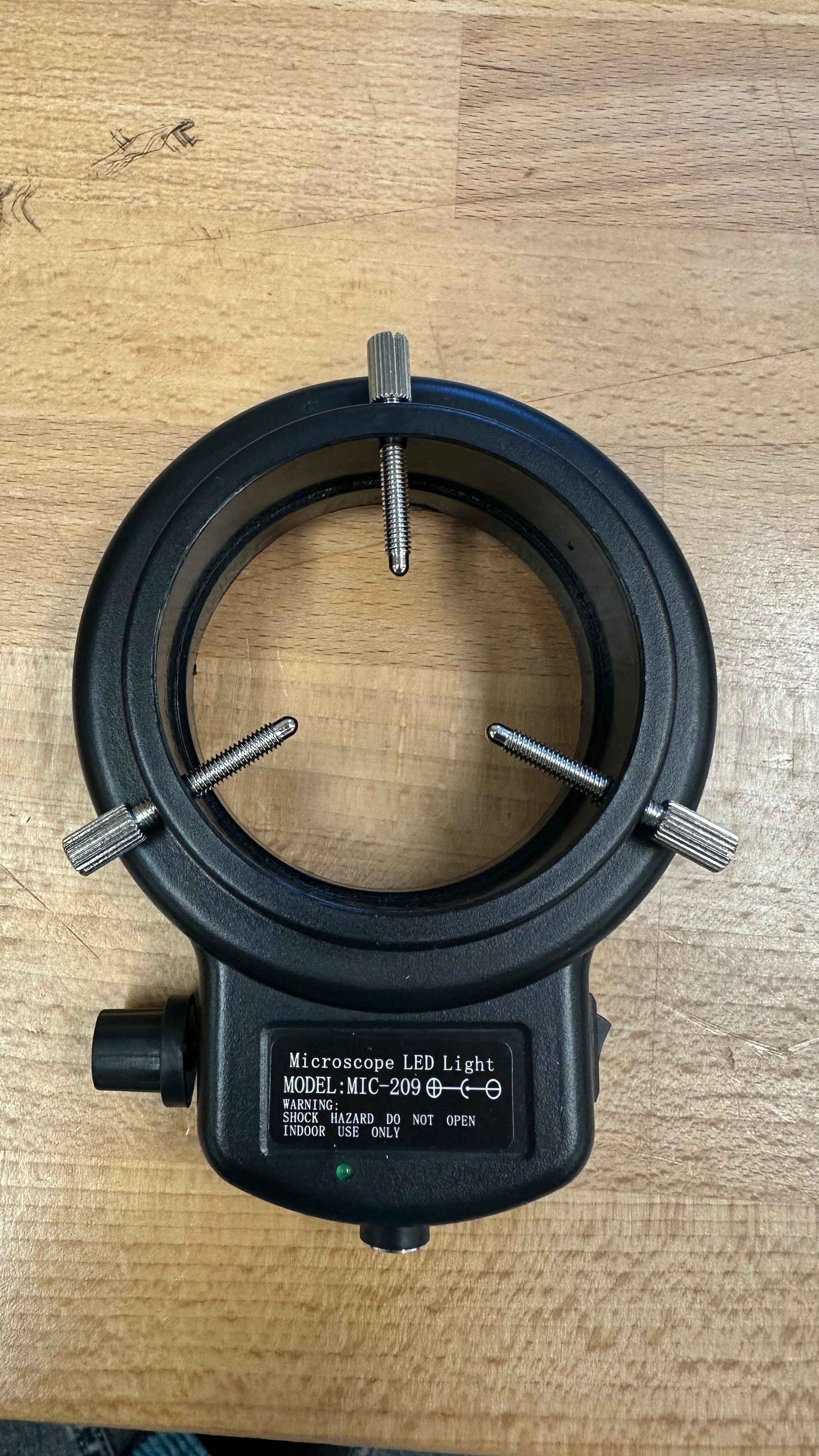
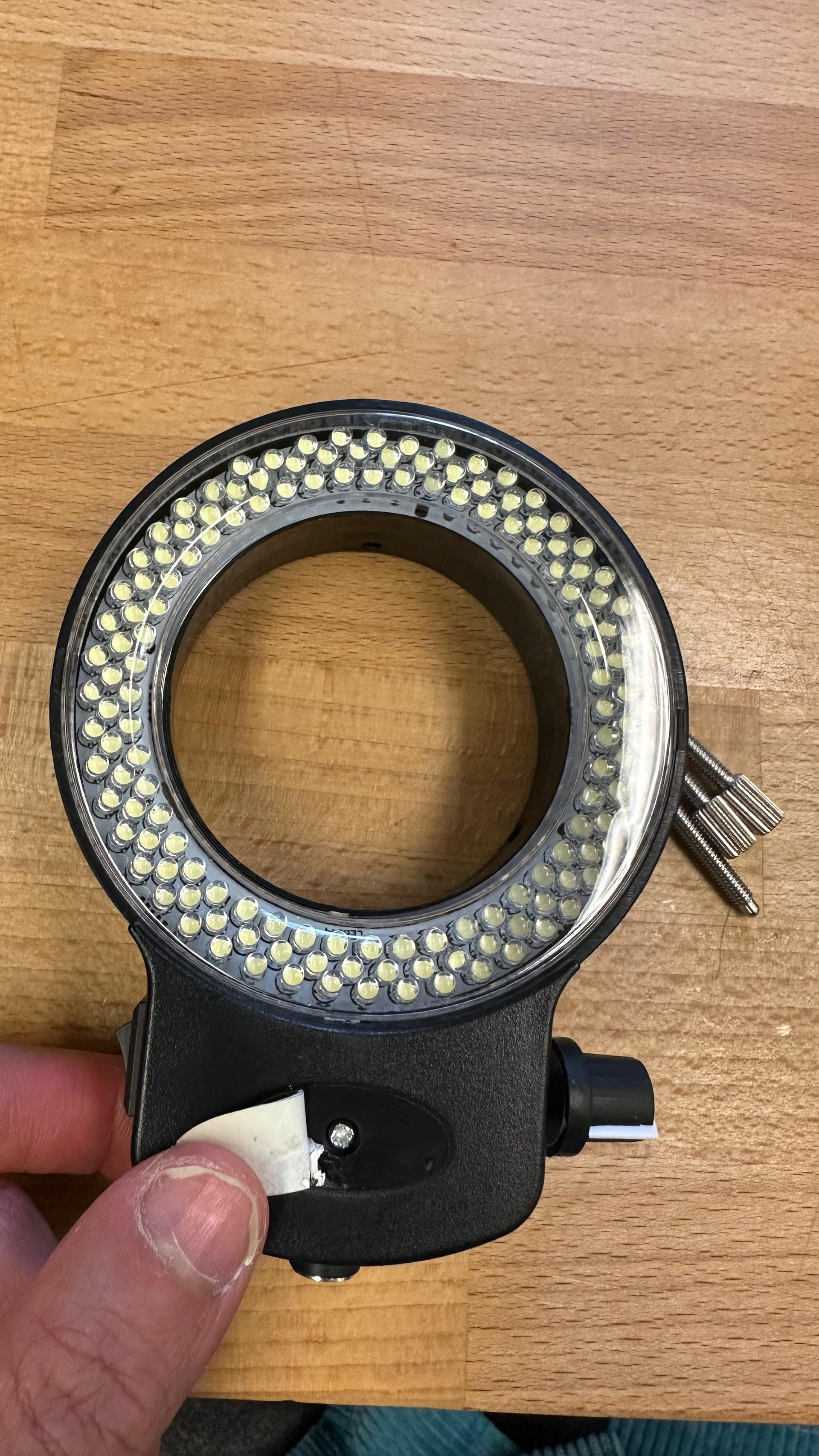
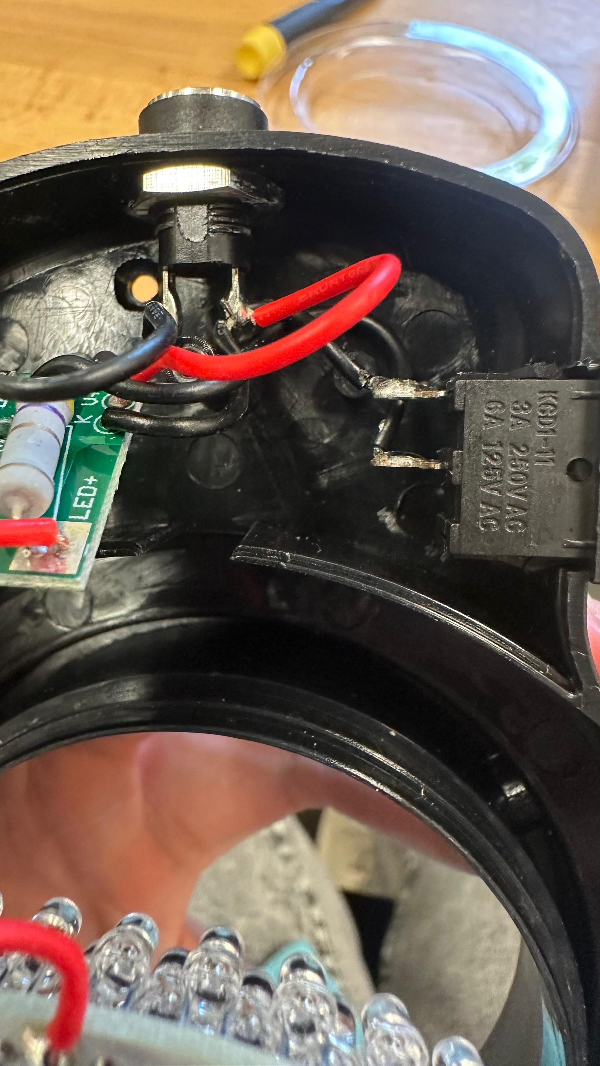
Start by removing the outer screws from the ring light housing. These screws are located around the side of the lamp body. Some of these screws can be loosened by hand, but a small screwdriver may also be useful.
After removing the outer screws, peel off the sticker on the housing. There is a small hidden screw underneath the sticker. Remove this screw as well. Once this screw is removed, the whole lamp housing can be opened.

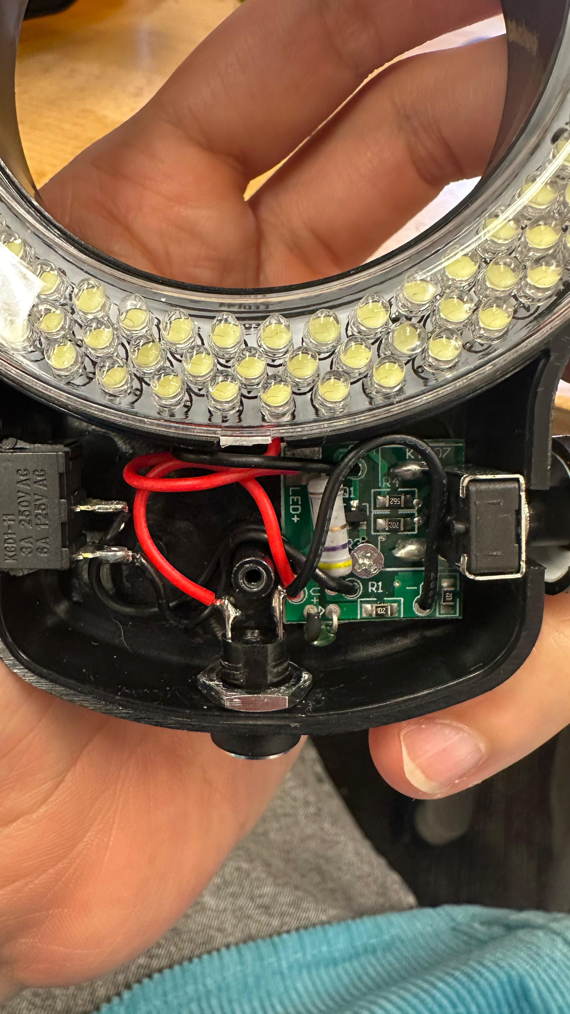
Inside the lamp, there is one screw holding the PCB in place. Remove this screw so the PCB and internal components become loose.

The only part that may still be attached is the power switch. The switch is not screwed in; it slides into the housing. To release it, gently slide or push the switch upward until it comes free.

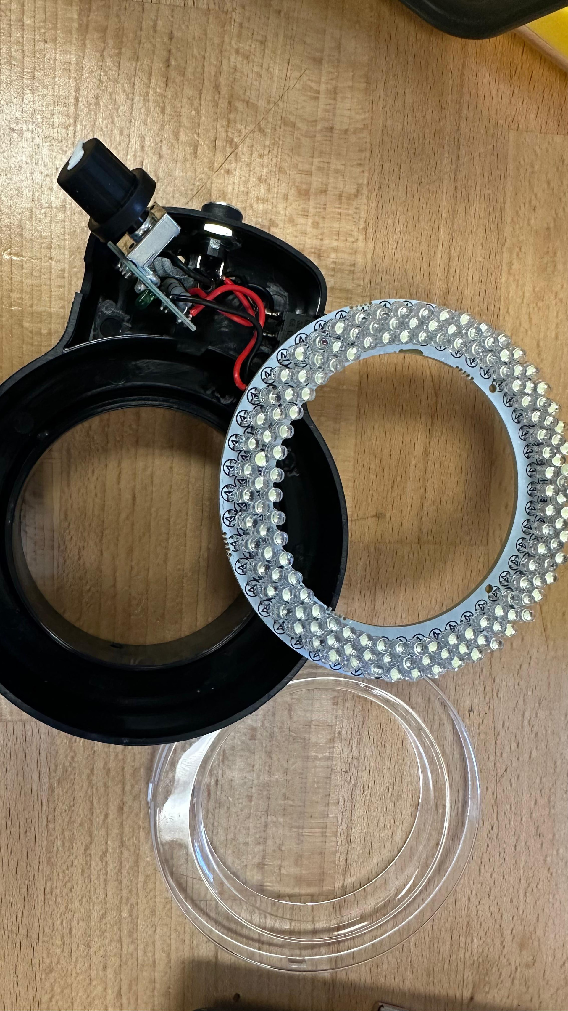
Next, use a flat screwdriver to carefully lift the lamp assembly out of the housing. Work slowly around the edges so the plastic does not crack and the internal parts do not get damaged.

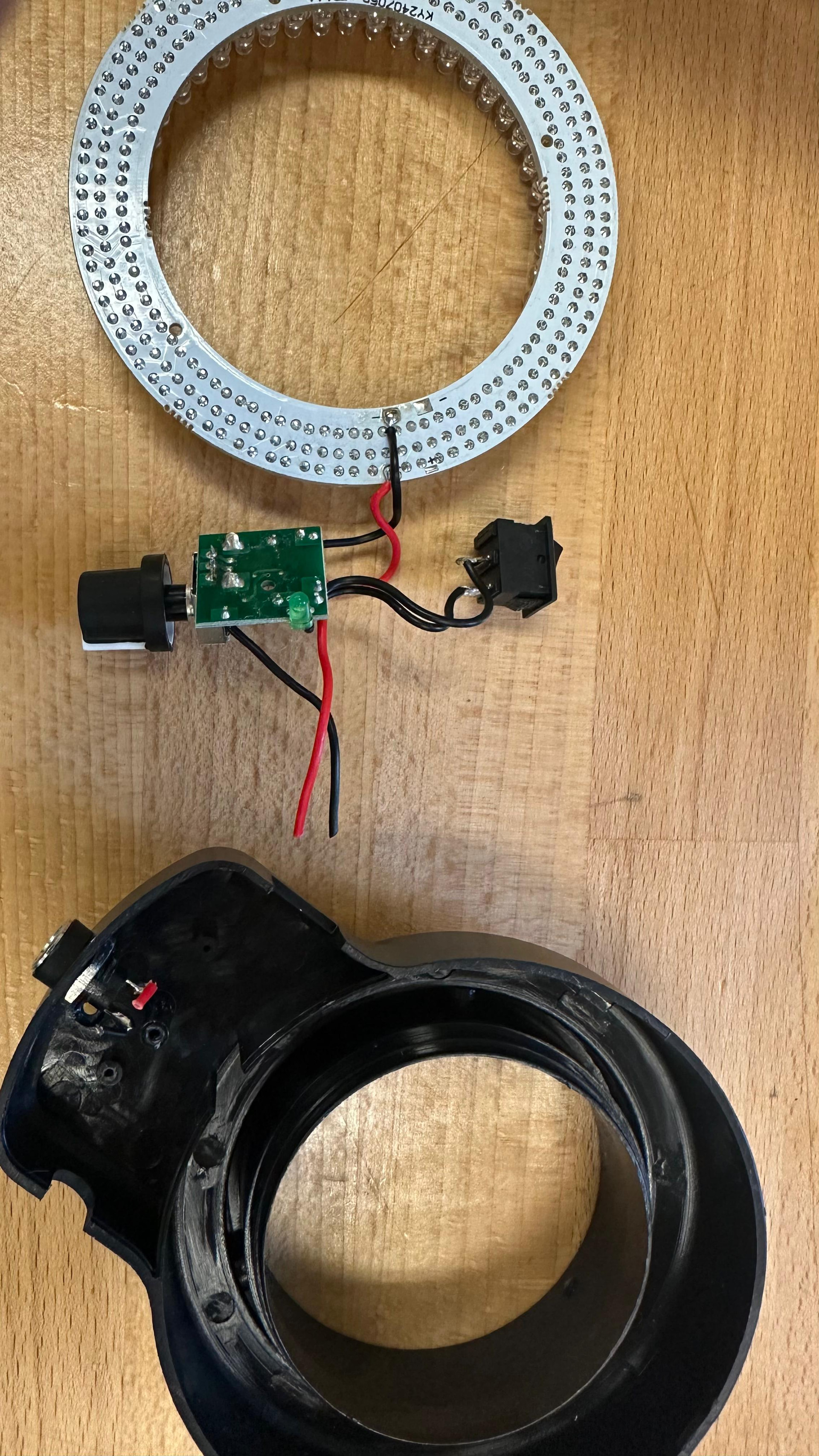
Once the lamp is removed, cut the wires connected to the power connector. Some ring lights have a barrel jack connector, while others use a USB cable.

After disassembly, the lamp housing, PCB, LED ring, switch, and power connector were separated. These parts can now be reused, studied, or measured for replication.


3. Mounting the Lamps to the Mainboard

After disassembling the ring lights, the next step was to attach both lamp assemblies to the mainboard.

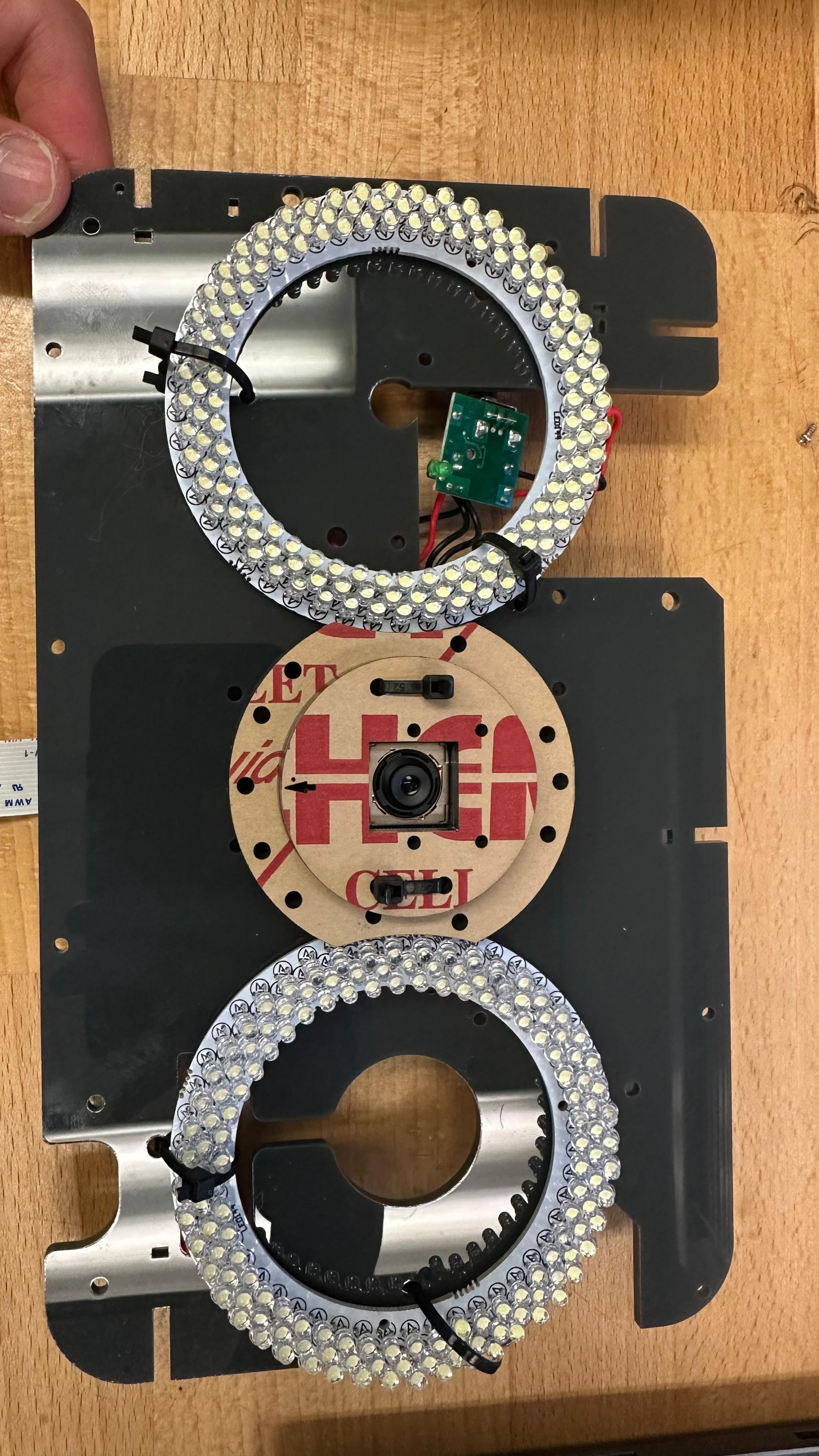
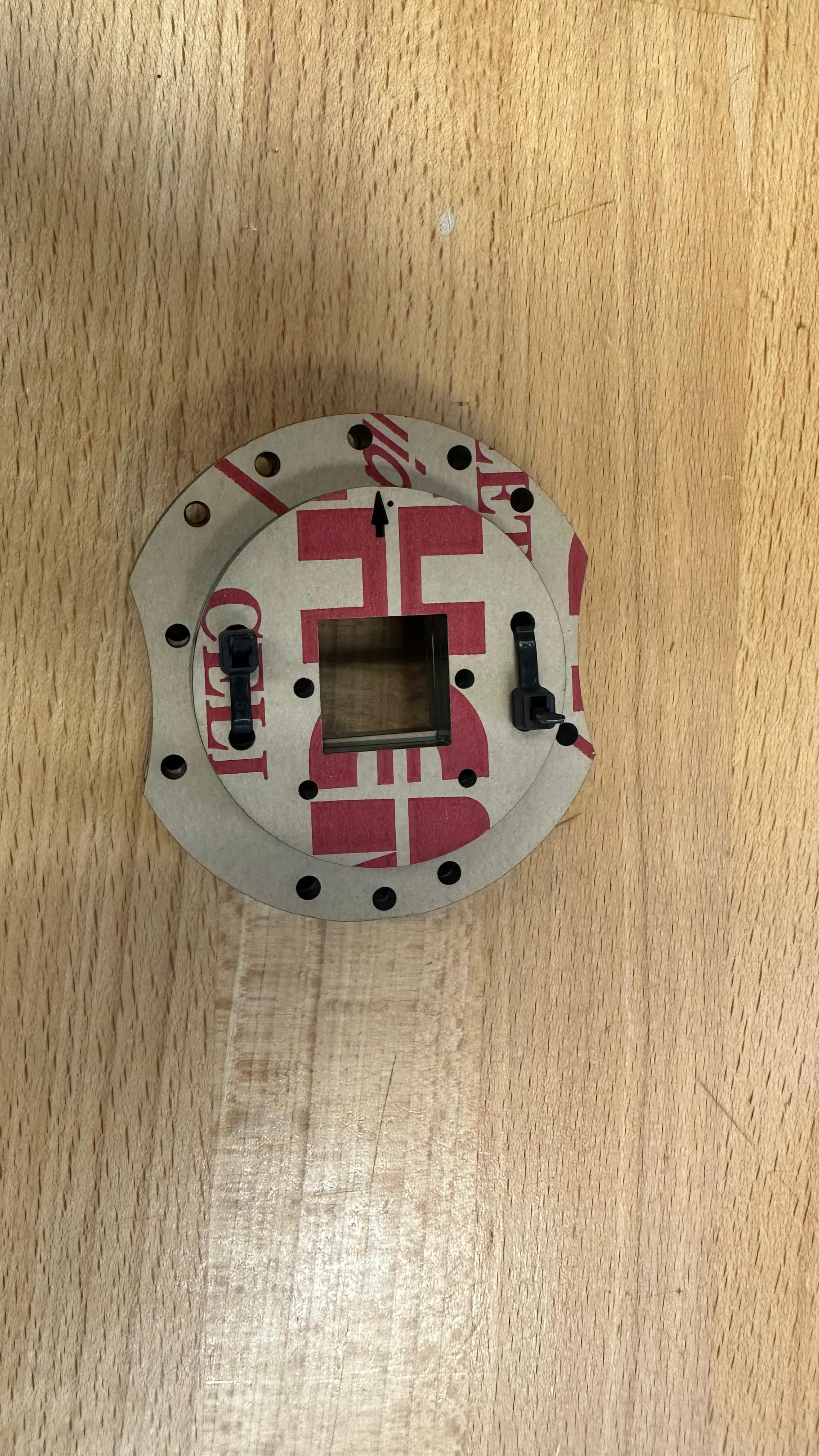
Position the two lamp assemblies on the mainboard in their correct locations. Once the lamps are aligned, secure them using zip ties.

Zip ties worked well for holding the lamps in place because they are easy to install, adjustable, and strong enough to keep the lamps stable during testing.

Do not fully tighten the zip ties immediately. First, make sure both lamps are centered, facing the correct direction, and not blocking any other mounting holes or components.

In the image above, the camera is not zip-tied yet. This is because the correct M2 screws and bolts were not available at the time.

These tiny screws are needed to properly secure the camera to the laser-cut parts. Since they were not available in the lab, the camera was left unsecured during this stage.

For the final build, make sure to order the M2 screws and bolts ahead of time. They are very small and may not be available in the lab.


4. Connecting the Raspberry Pi to the Mainboard

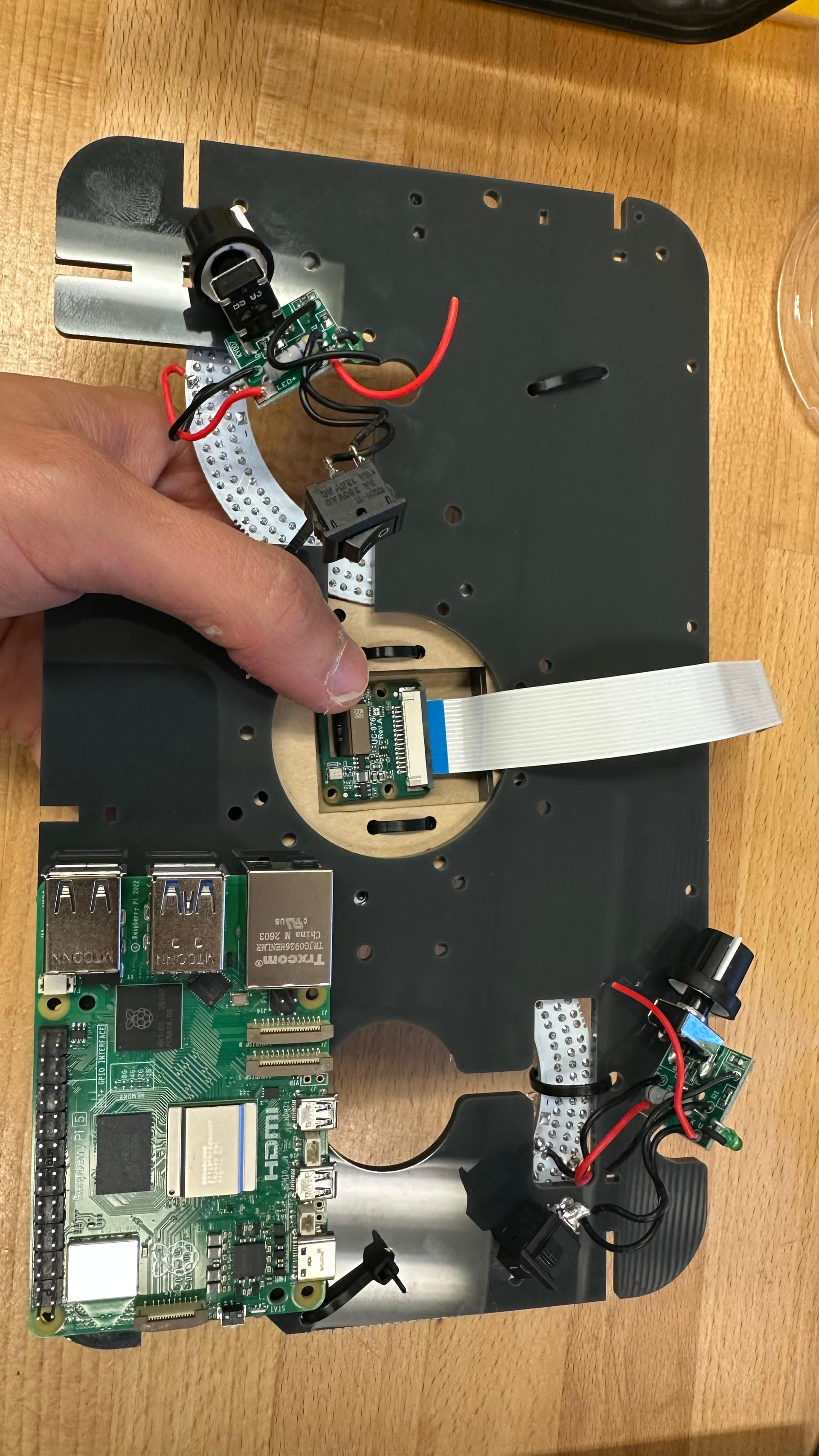
The next step was to mount the Raspberry Pi to the mainboard.

The original documentation says that the Raspberry Pi sits in the corner of the mainboard. It also says that the Raspberry Pi connection points have a tiny extra hole next to them, which is supposed to help identify the correct holes for mounting the Raspberry Pi.

However, during this assembly, those tiny extra reference holes were not visible.

Procedure

Place the Raspberry Pi in the corner of the mainboard. Since the tiny extra reference holes were not visible, use the Raspberry Pi mounting-hole pattern and the corner position of the mainboard to align it.

When trying to attach the Raspberry Pi, I realized that one of the zip ties holding the lamp was blocking one of the Raspberry Pi mounting holes. To fix this, I had to open or loosen that zip tie, move the lamp slightly, and reposition the zip tie so the mounting hole was clear.

After moving the zip tie and clearing the hole, align the Raspberry Pi again. Once the Raspberry Pi is correctly positioned and all mounting holes are clear, secure it using the appropriate screws and spacers (We don’t have the screws so I will post a picture here after getting them).

5. Drilling the Mothbox Holes

Overview

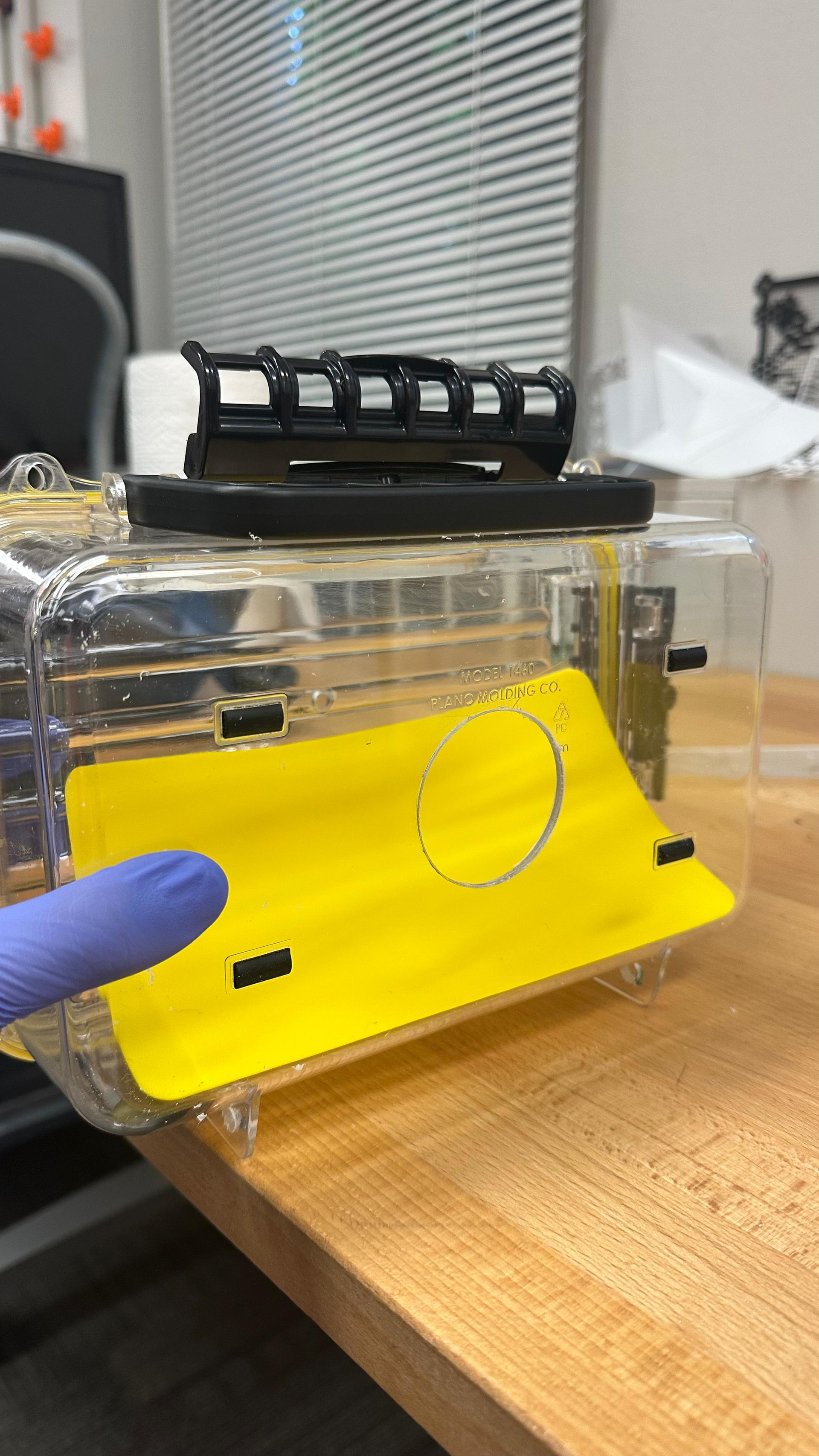
Today I started drilling the holes in the Mothbox enclosure. This included drilling the front lens hole and the holes for attaching the mounting arms.

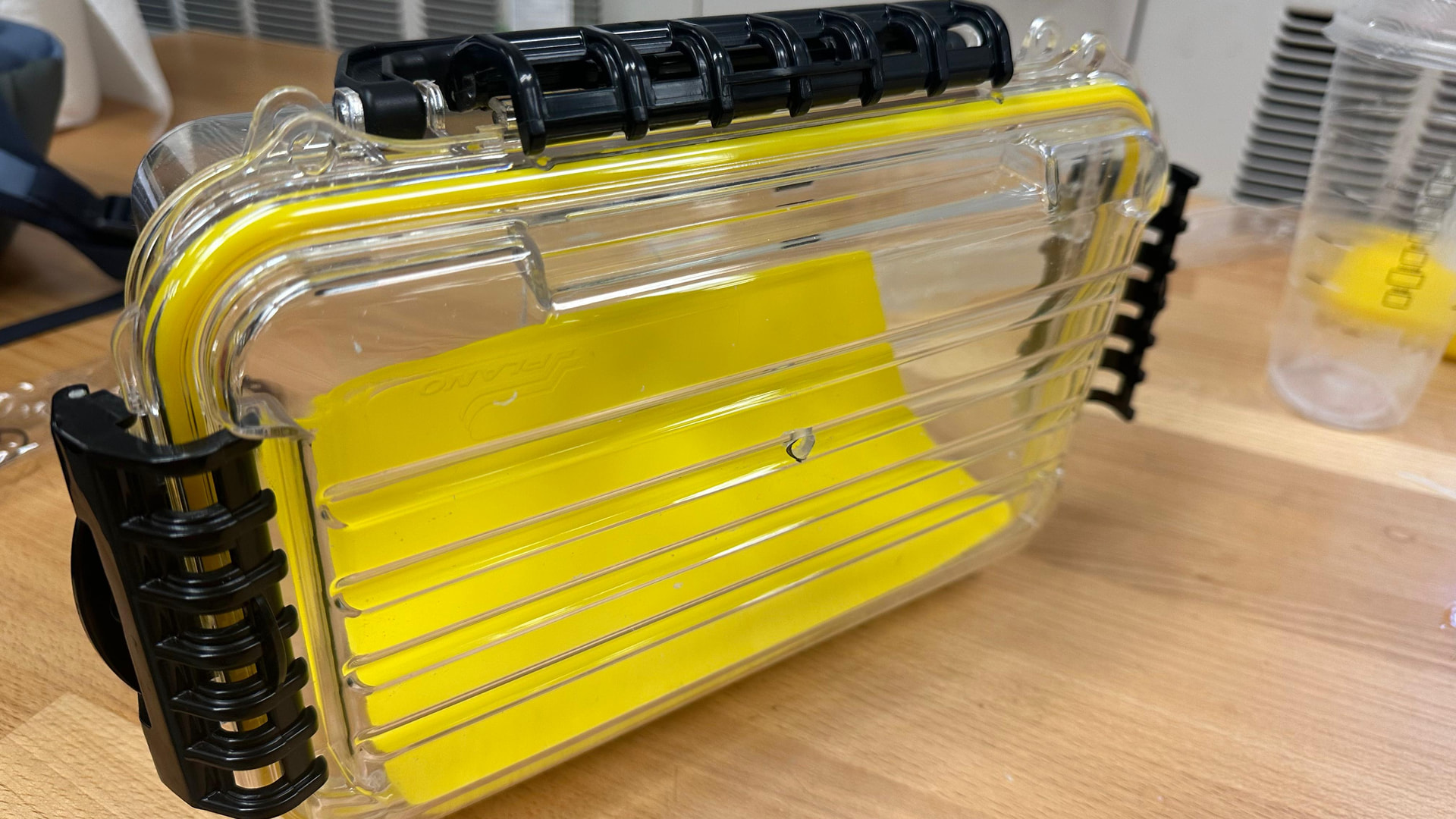
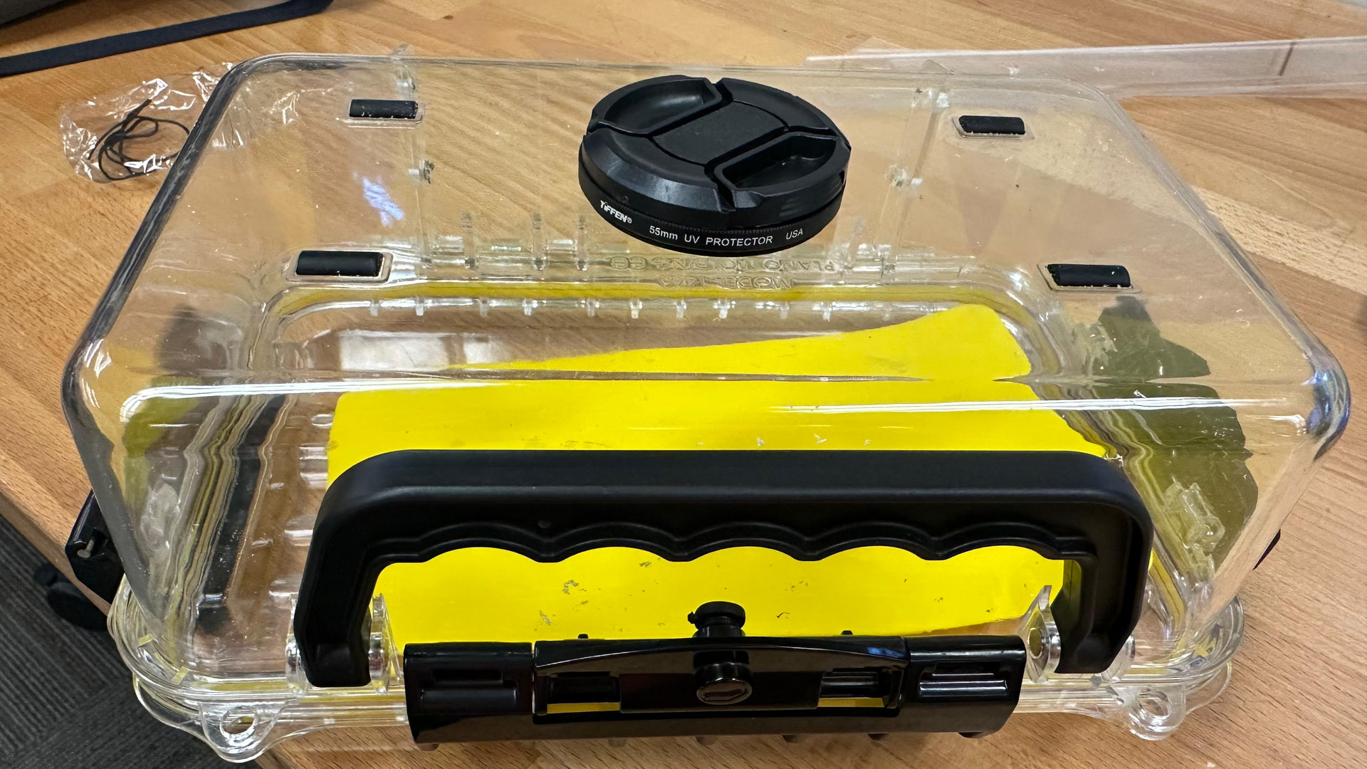
The original tutorial says that the box has a small dot in the center of the back side, which can be used as a reference point for drilling the front lens hole. However, I initially misunderstood which side of the box needed to be drilled and accidentally drilled the hole on the wrong side.

The correct side for the front lens hole is the back of the box, not the side with the ridges.


Drilling the Front Lens Hole

To make the front lens hole, first locate the small center dot on the back of the box. This dot marks the center point for the lens opening.

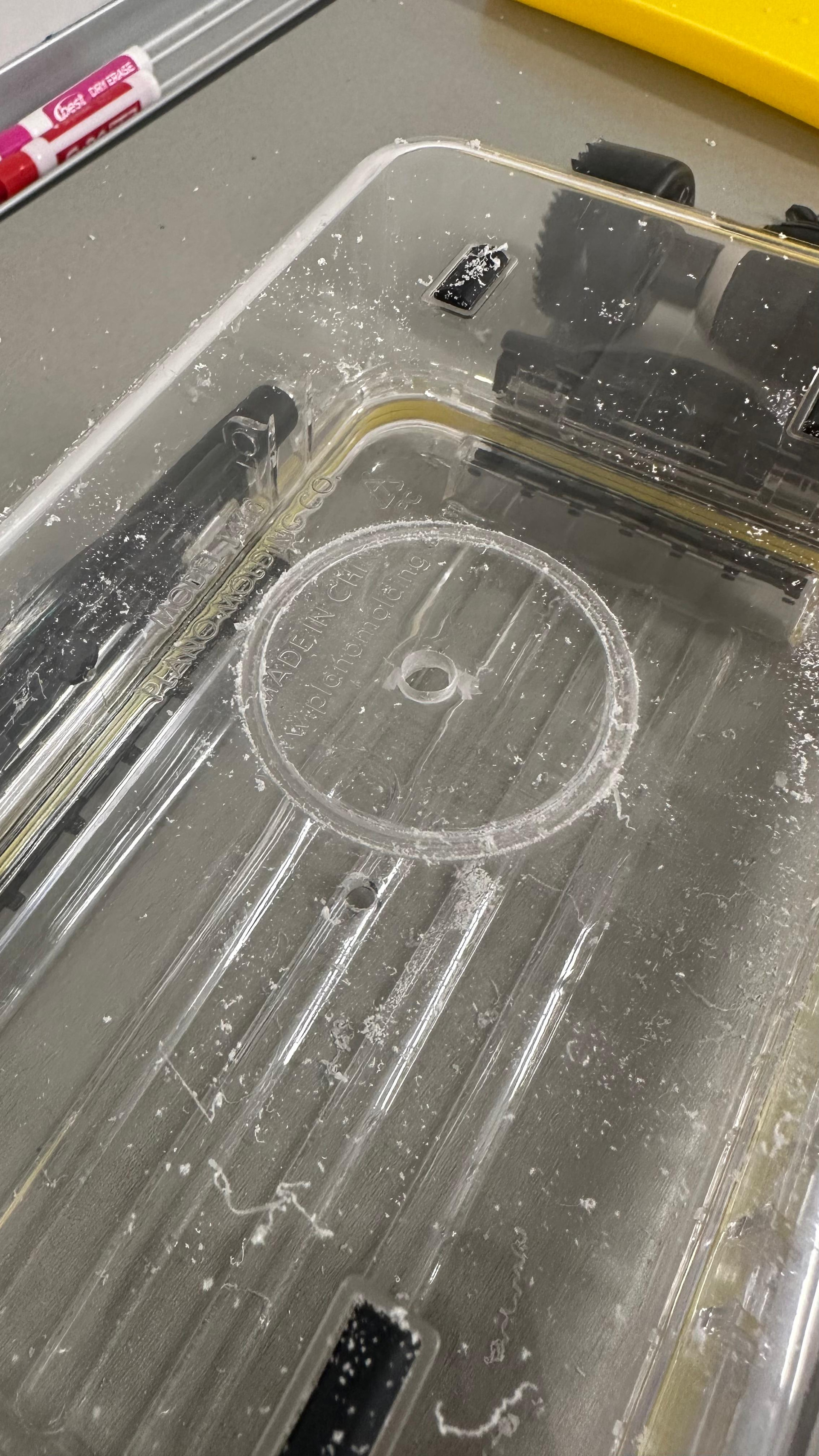
Start by drilling a small pilot hole. Use light pressure while drilling because the plastic box can crack if too much force is applied.

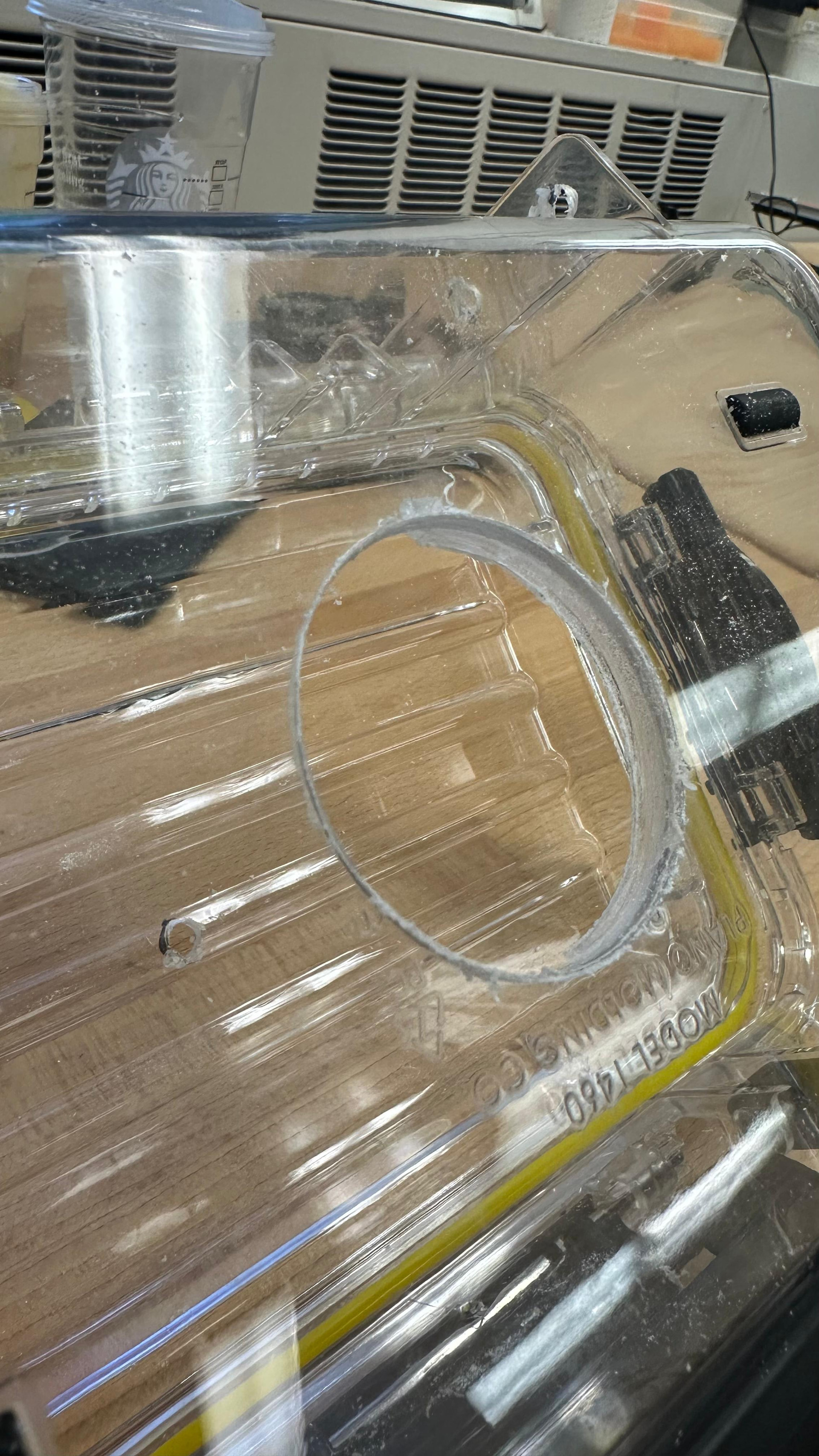
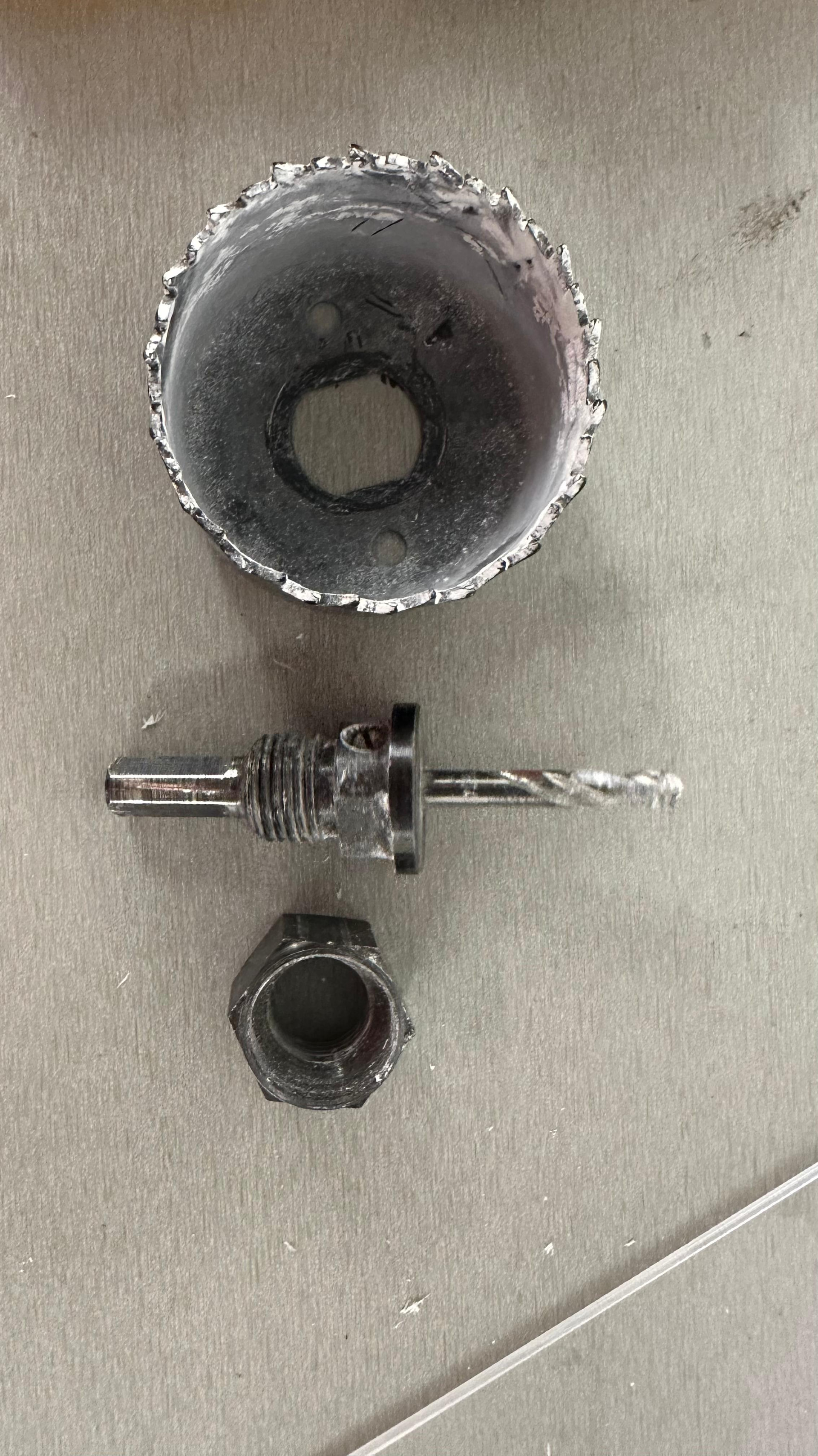
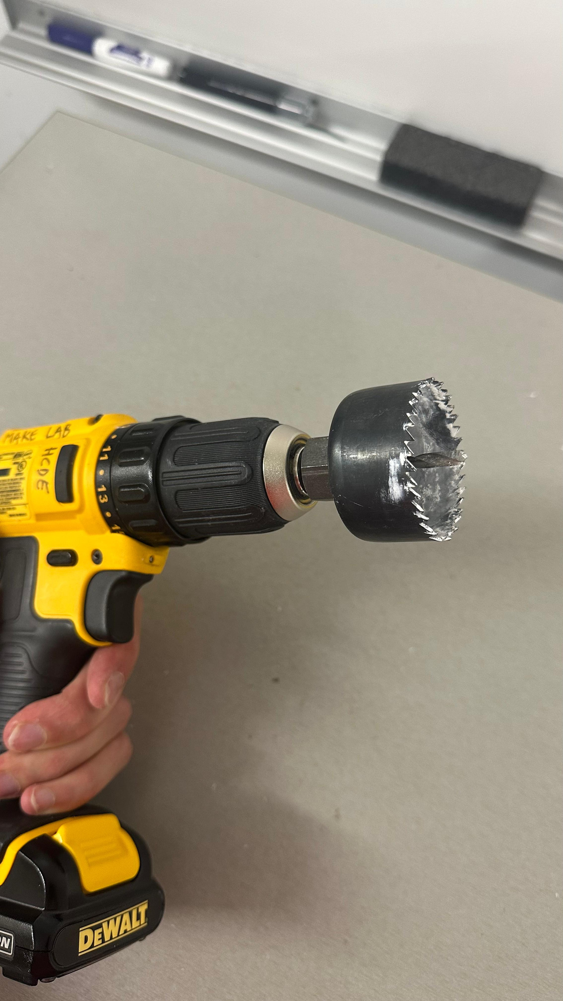
After making the pilot hole, use the larger hole cutter bit. The tutorial specifies a 53 mm hole cutter bit for this step. DO NOT push at all. Apply small force!

After drilling, the edge of the hole was not perfectly clean. This is expected, so use a sharp tool to clean up the rough plastic edges.

This was my first time using this type of hole cutter bit, so I had to figure out how it works. The bit has a center nub or pilot section that helps keep the cutter centered while the larger circular blade cuts the hole.

Drilling the Arm Mounting Holes

I also drilled the holes for attaching the arms to the box.

The tutorial suggests using a drill bit slightly larger than 1/4 inch, such as 5/16 inch, because the holes may not line up perfectly if the measuring or drilling is slightly off.

In my case, the holes did not align perfectly because the drill bit moved a little while drilling. To avoid this, it may help to hold the arm directly against the box while drilling. This way, the holes in the box are more likely to match the holes in the arm.

6. Preparing the Lens Adapter / Lens Protector

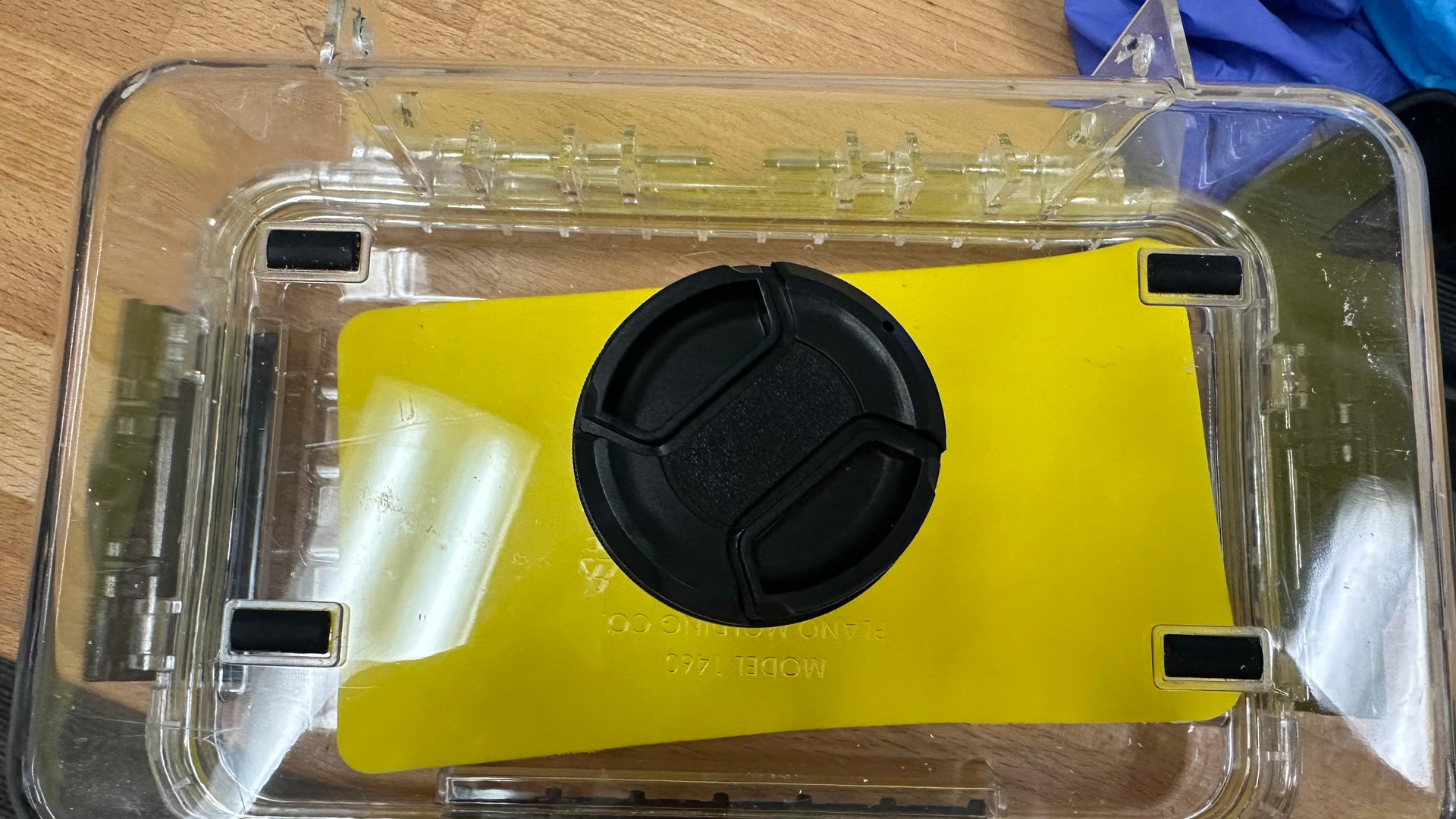
After drilling the front lens hole, the next step is to attach the lens part to the box using epoxy.

However, I did not have epoxy available in the lab, so this step could not be completed yet.

The tutorial says to add the lens adapter and use a thin stick to help the epoxy seep into the seam between the lens connector and the box. It also says to look for air bubbles coming from the seam.

However, I found this part of the documentation unclear because the materials list includes several lens-related parts:

Camera lens gear

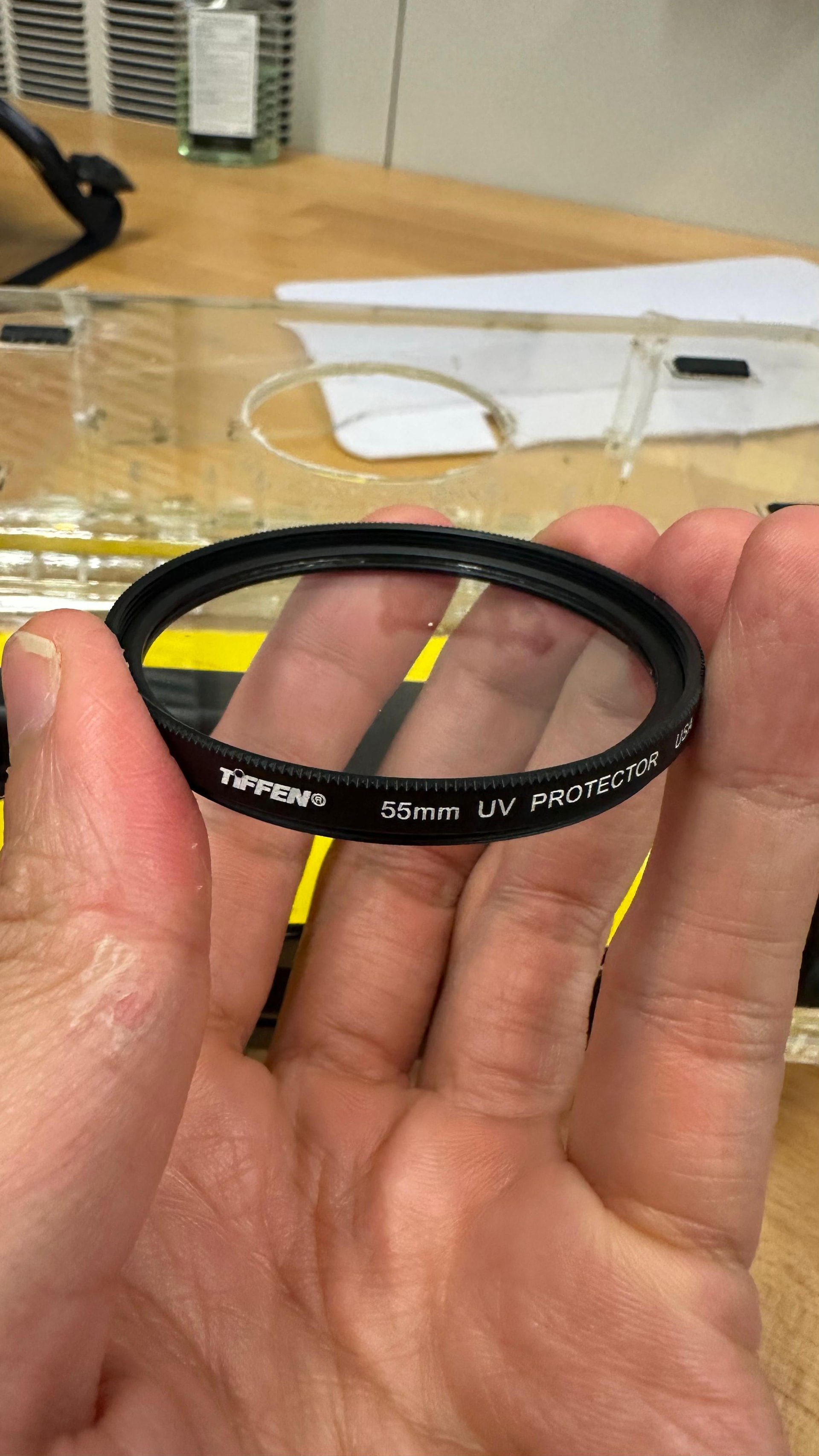
UV lens protector and mount

Lens rings

UV filter

Lens hood

The document refers to a “lens adapter,” but it is not immediately clear which of these parts is the lens adapter.

Question About the Lens Adapter

At this stage, I assumed that the “lens adapter” might be the lens protector or mount, but I was not completely sure.

I was also unsure whether this part should sit inside the drilled hole or on top of the hole. Another unclear point was which side of the lens part should be glued to the box.

To figure out the correct orientation, I placed the lens cover on the part and checked which side the cover attaches to. Based on this test, I assumed that the side where the lens cover attaches should face outward and should not be glued directly to the box.


1 Like

6. Attaching the Lens to the Box

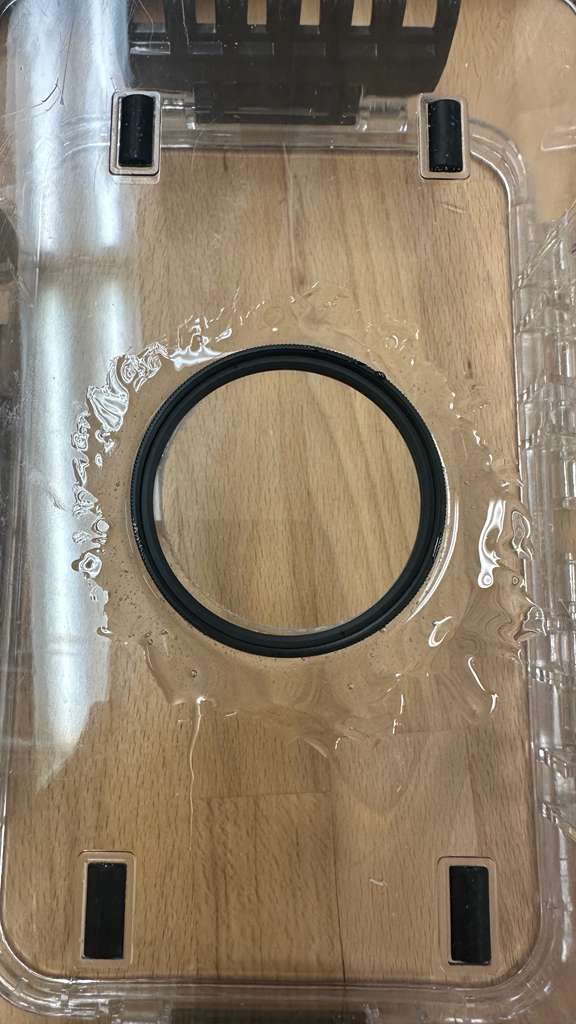
This week, I finally got epoxy and attached the lens piece to the box.

After confirming the orientation, I placed the lens part over the drilled hole and used epoxy to secure it to the box. The side where the lens cover attaches should face outward so the cover can still be used after installation.

One tip is to wait until the epoxy becomes slightly thicker before applying it. If it is too runny, it can spread too much and flow away from the seam. However, do not wait too long, because once the epoxy starts curing too much, it will lose its ability to bond properly.


7. Installing the Raspberry Pi

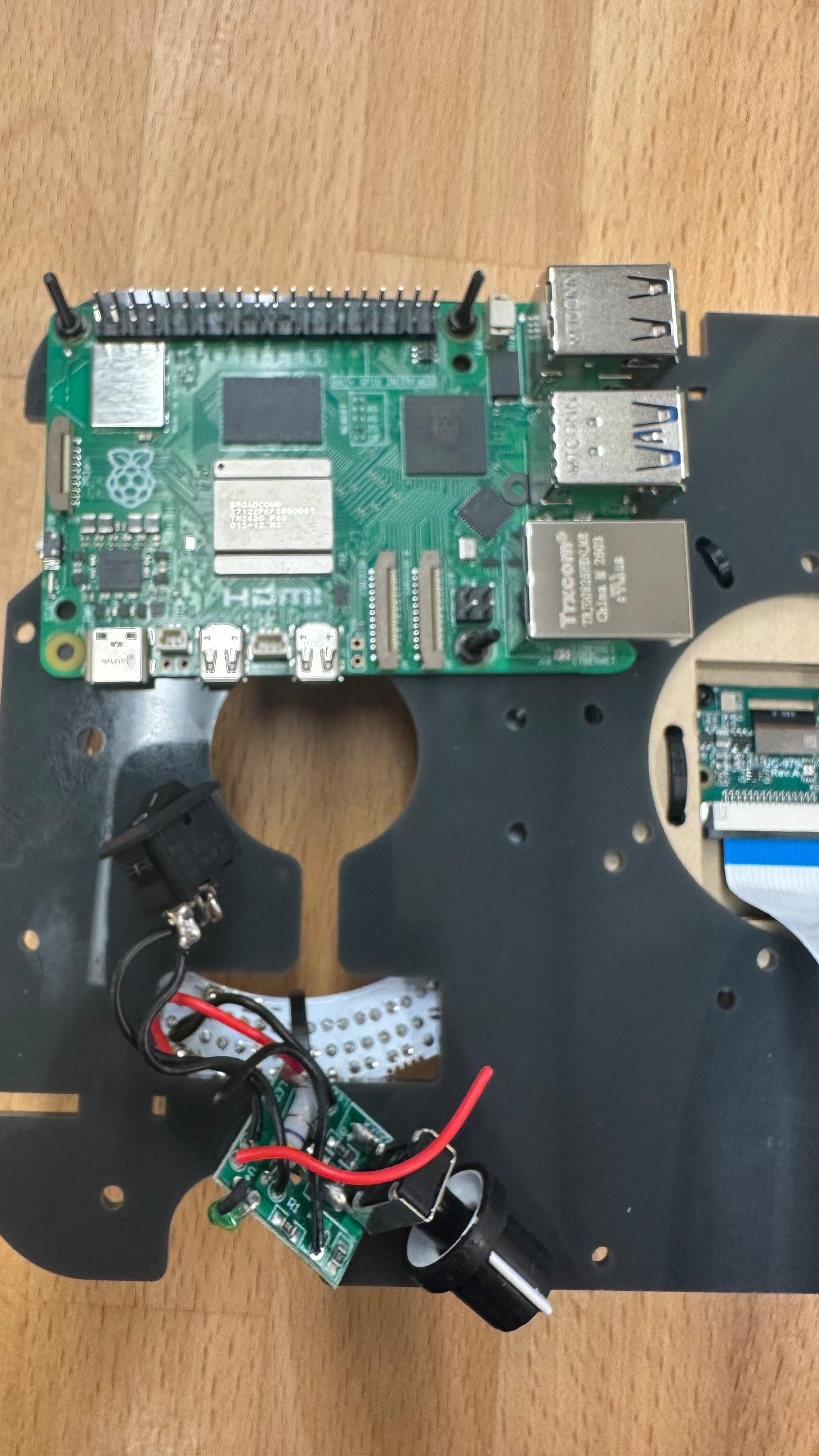
I also installed the Raspberry Pi on the mainboard.

Previously, I was missing the correct screws, so I could not secure the Raspberry Pi properly. After getting the screws, I mounted the Raspberry Pi in its correct position on the board.


8. Camera Cable Issue

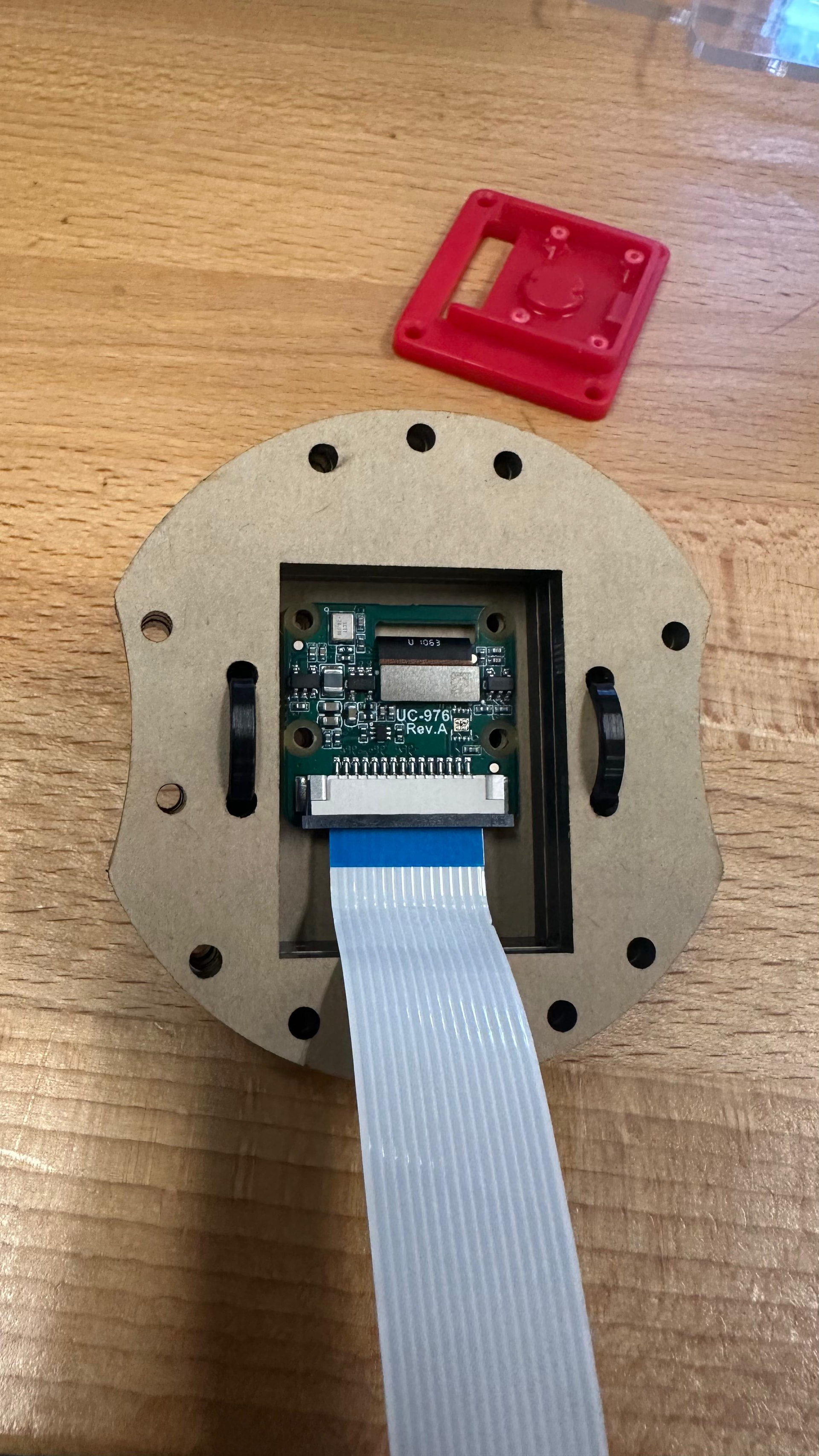
The next step is connecting the camera to the Raspberry Pi.

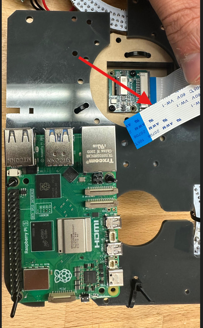
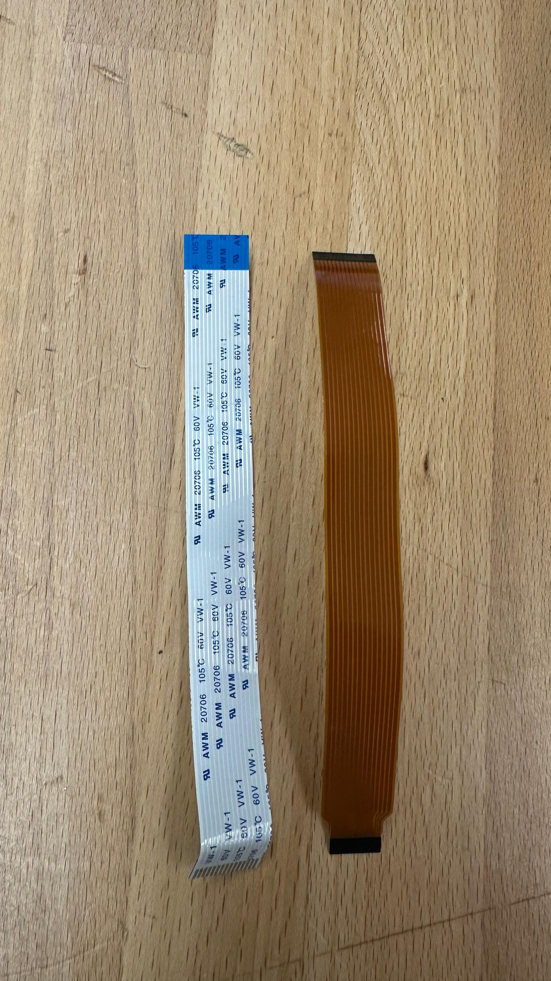
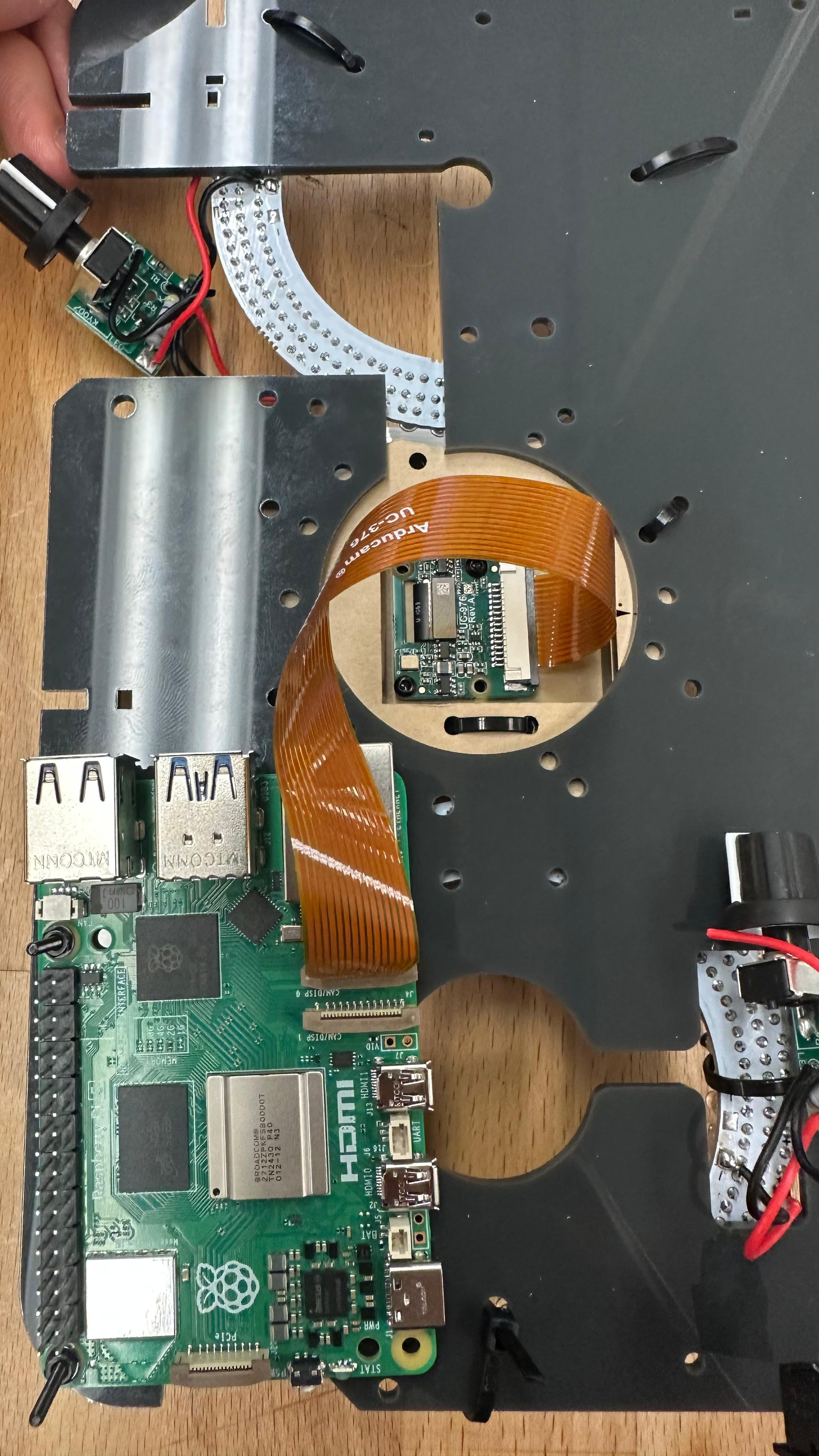
The camera came with a cable already attached, but that cable does not fit into the Raspberry Pi camera connector. However, inside the camera box, there was another cable included.

To connect the camera to the Raspberry Pi, remove the original camera cable and replace it with the extra cable from the camera box.

Switch the cable before connecting the camera to the Raspberry Pi.

9. Installing the Relay Board on the Raspberry Pi

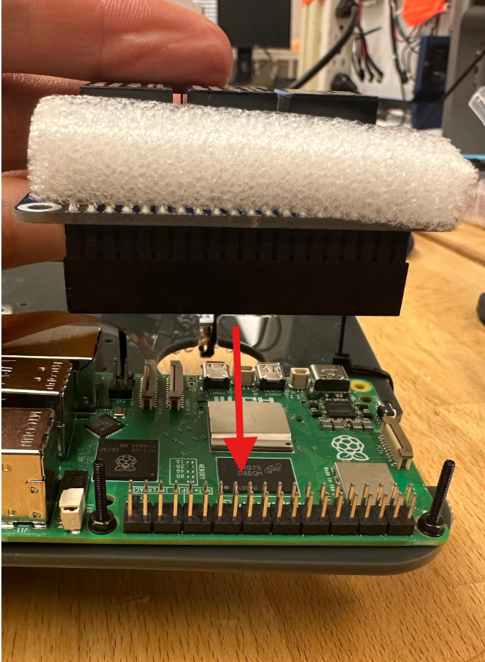
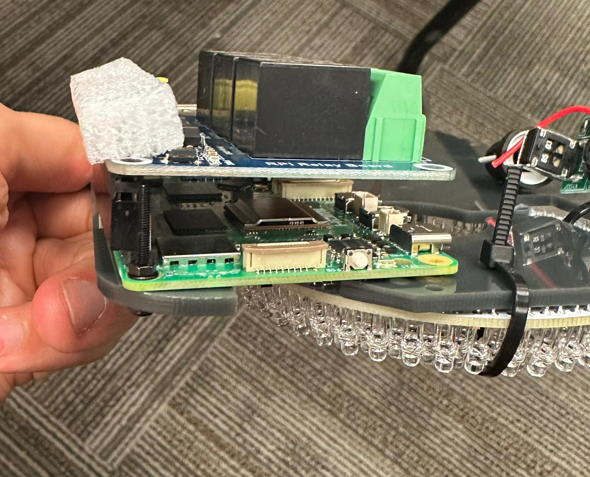
Next, I installed the relay board on top of the Raspberry Pi.

I followed the instructions from the tutorial link, and this step worked well without any problems. The relay board lined up correctly and attached to the Raspberry Pi as expected.

Make sure pins are lining up:


10. Connecting the Battery to the Board

After installing the relay board, I connected the battery to the board.

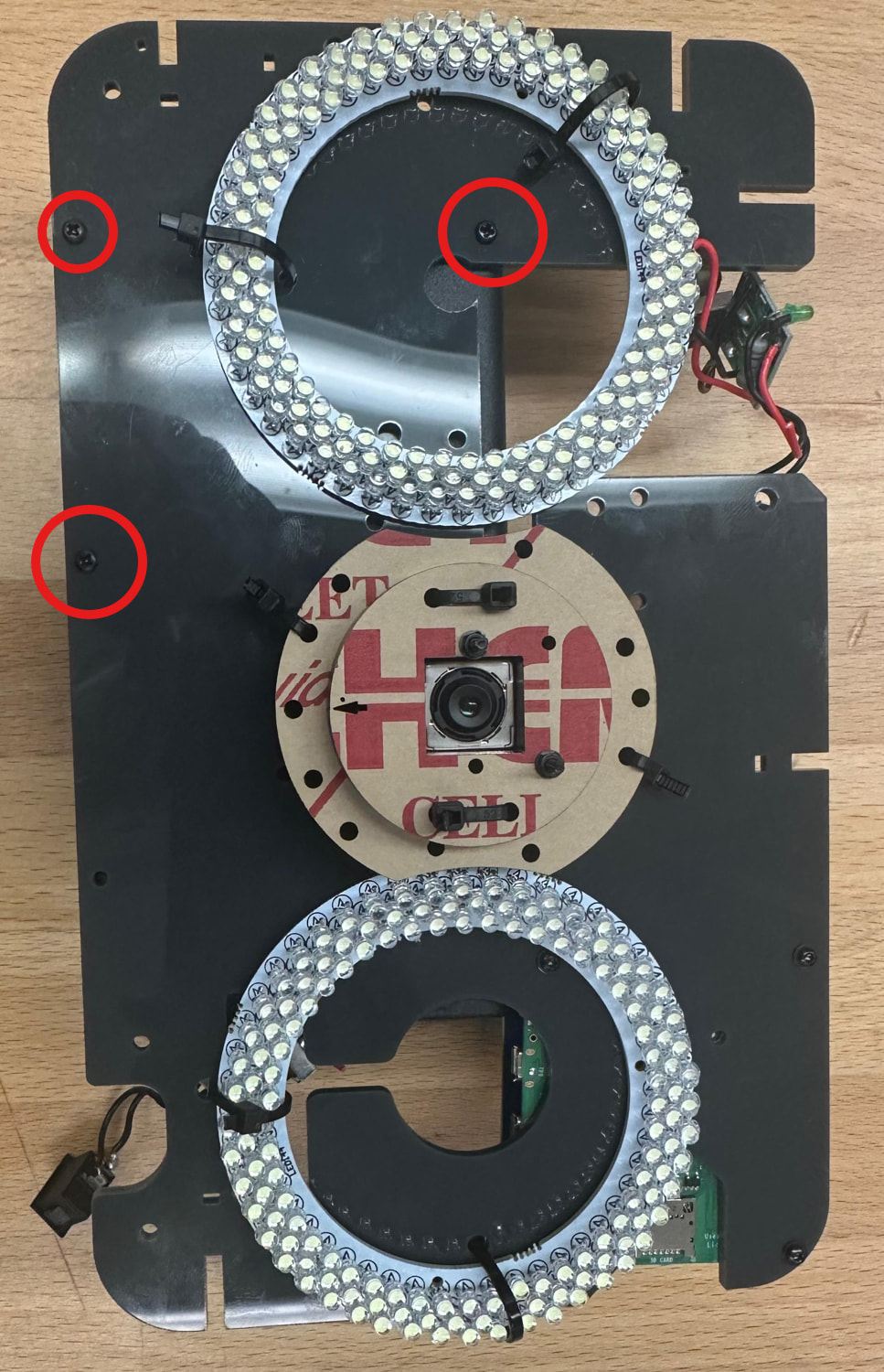
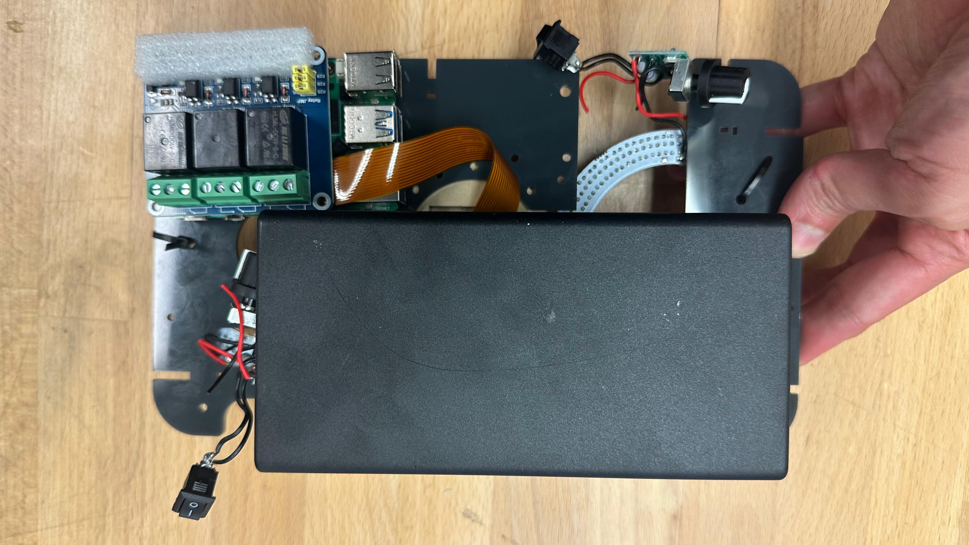
To do this, I opened the battery housing by removing the screws. Then I attached the battery back onto the board. This step worked fine and did not cause any issues.

I circled the holes where I screwed the battery case to the board. Not all of the holes in the battery case lined up perfectly with the holes in the board, but after adjusting it slightly, I was able to align and secure three of them.


11. Attaching the Extension arms to the Board

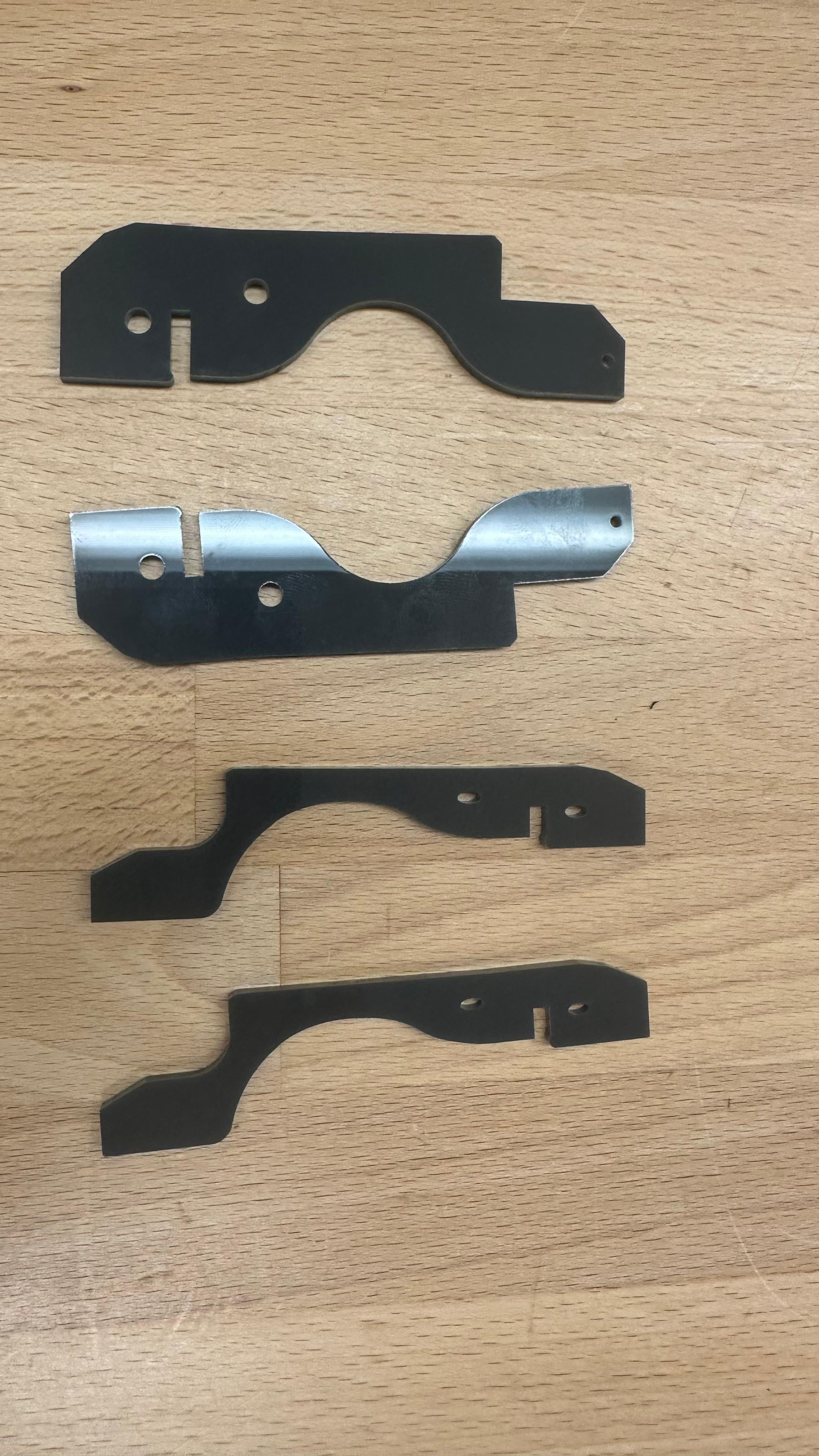
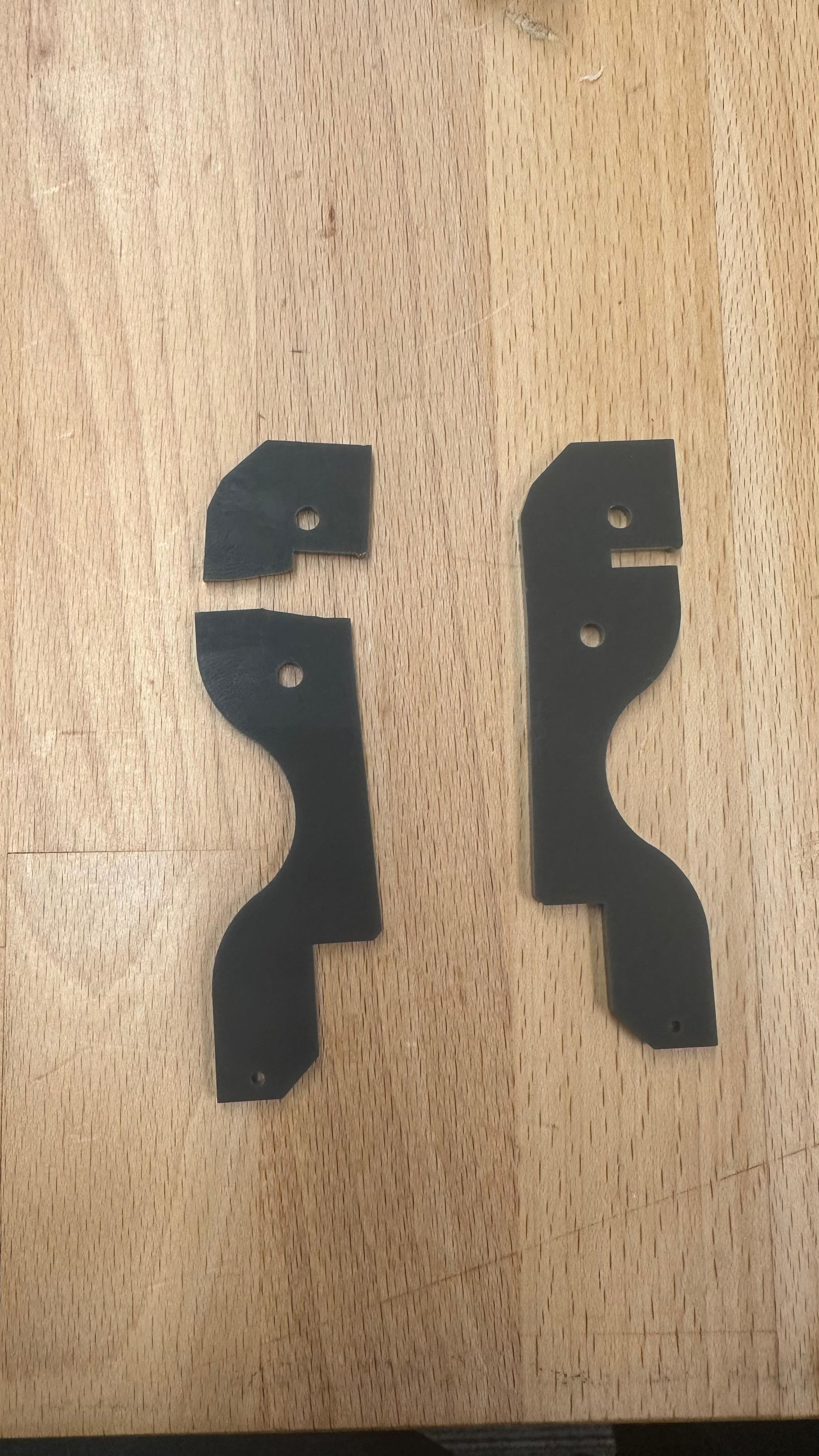
The next step was attaching the extension pieces to the board. These included two thicker pieces and two thinner pieces.

When I first tried to attach them, they did not fit perfectly into the board. I tried to wiggle the piece into place, but while doing that, part of the plastic broke.

To fix this, I had to cut the piece again. A better way to avoid breaking it is to slightly trim the corner with a sharp tool before forcing it into place.

After cutting the corner a little, the piece fit properly into the board.

Tips and Notes

Do not force the extension pieces if they do not fit at first.

Avoid wiggling the plastic too much because it can break.

If the piece does not fit, trim the corner slightly with a sharp tool.

After trimming, test the fit again gently.

It is unclear why the piece did not fit on the first try, but trimming the corner made it work.

12. Wiring the Components

Next, I connected all the wires following the main guidelines.

This step was clear and I did not run into any problems. I followed the wiring instructions exactly as described in the guide and connected everything accordingly.


13. Preparing the Internal 12V UV Light

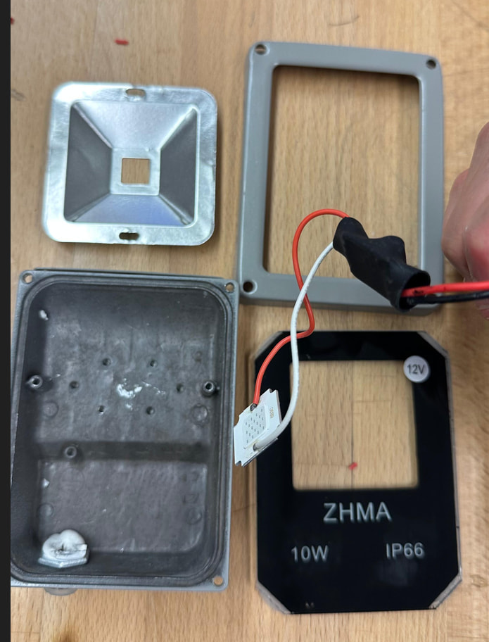
After wiring, I opened the internal 12V UV light.

This is the light listed in the guide under the Attractor tab for the internal 12V UV light. I used the same light from the guide.

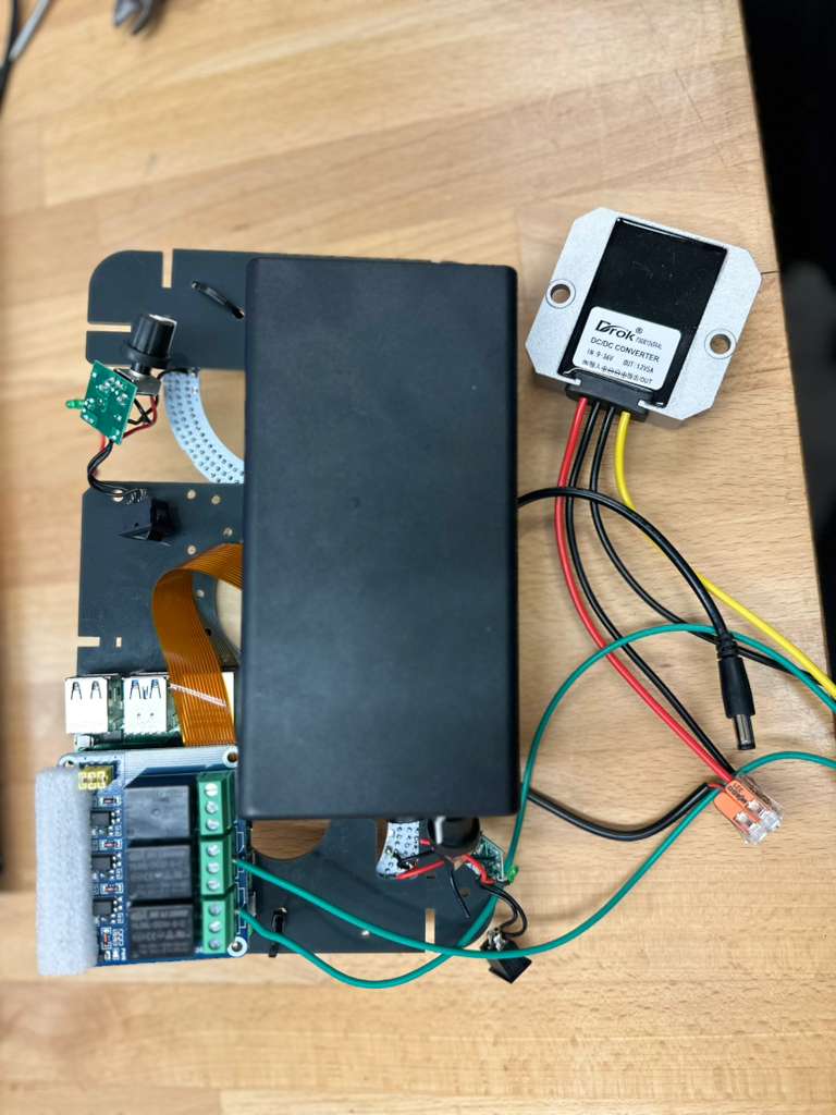
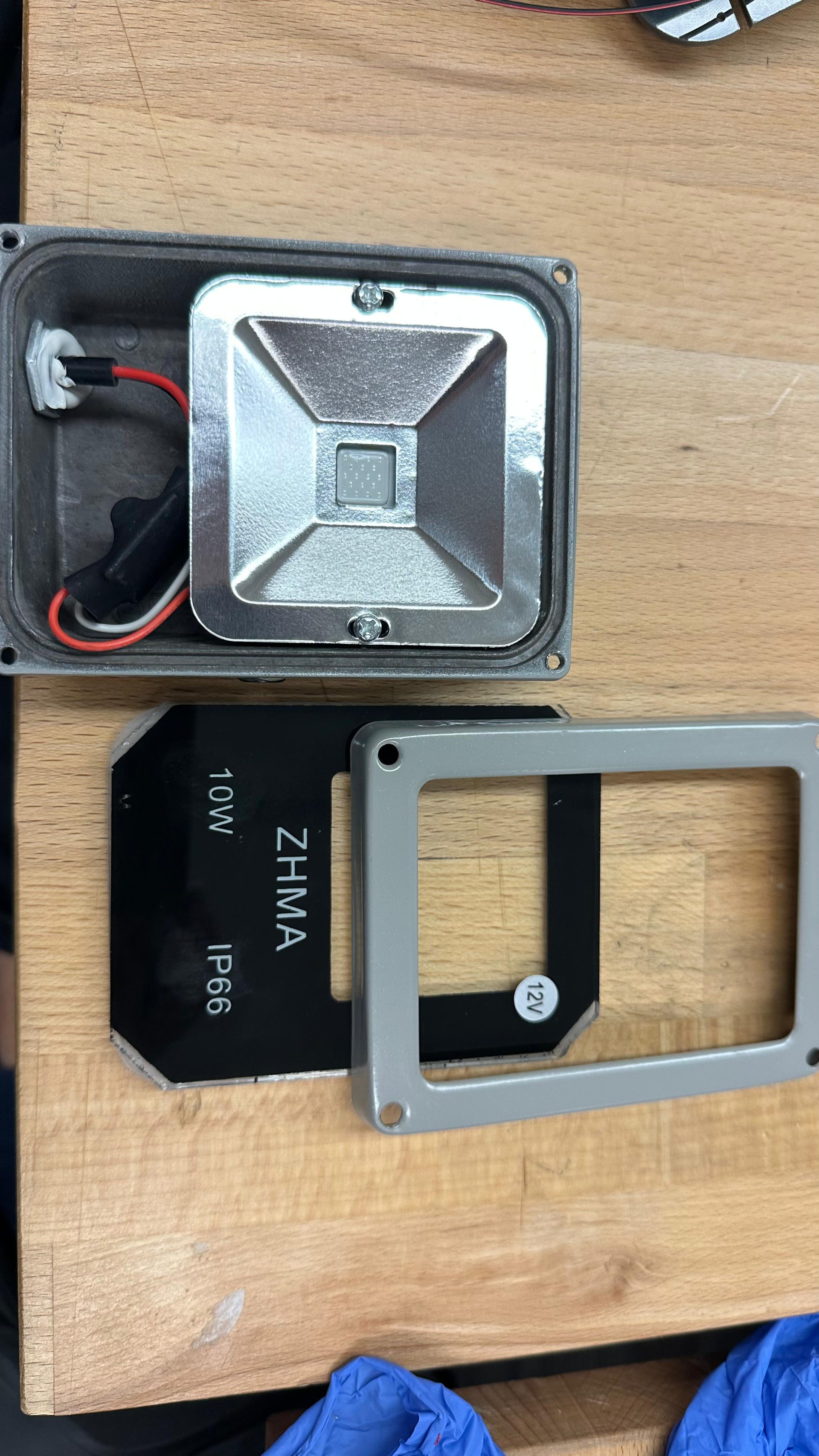
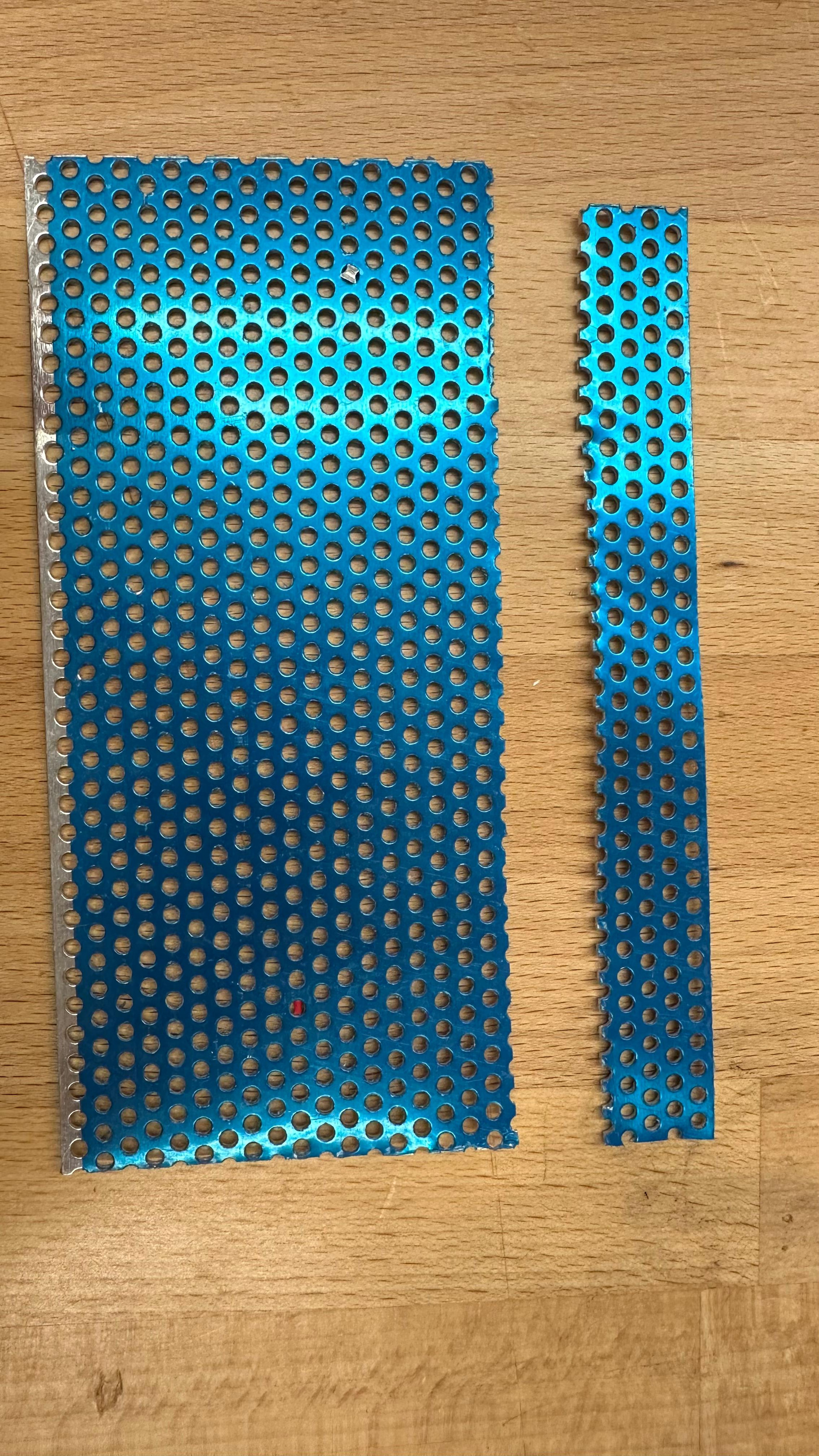
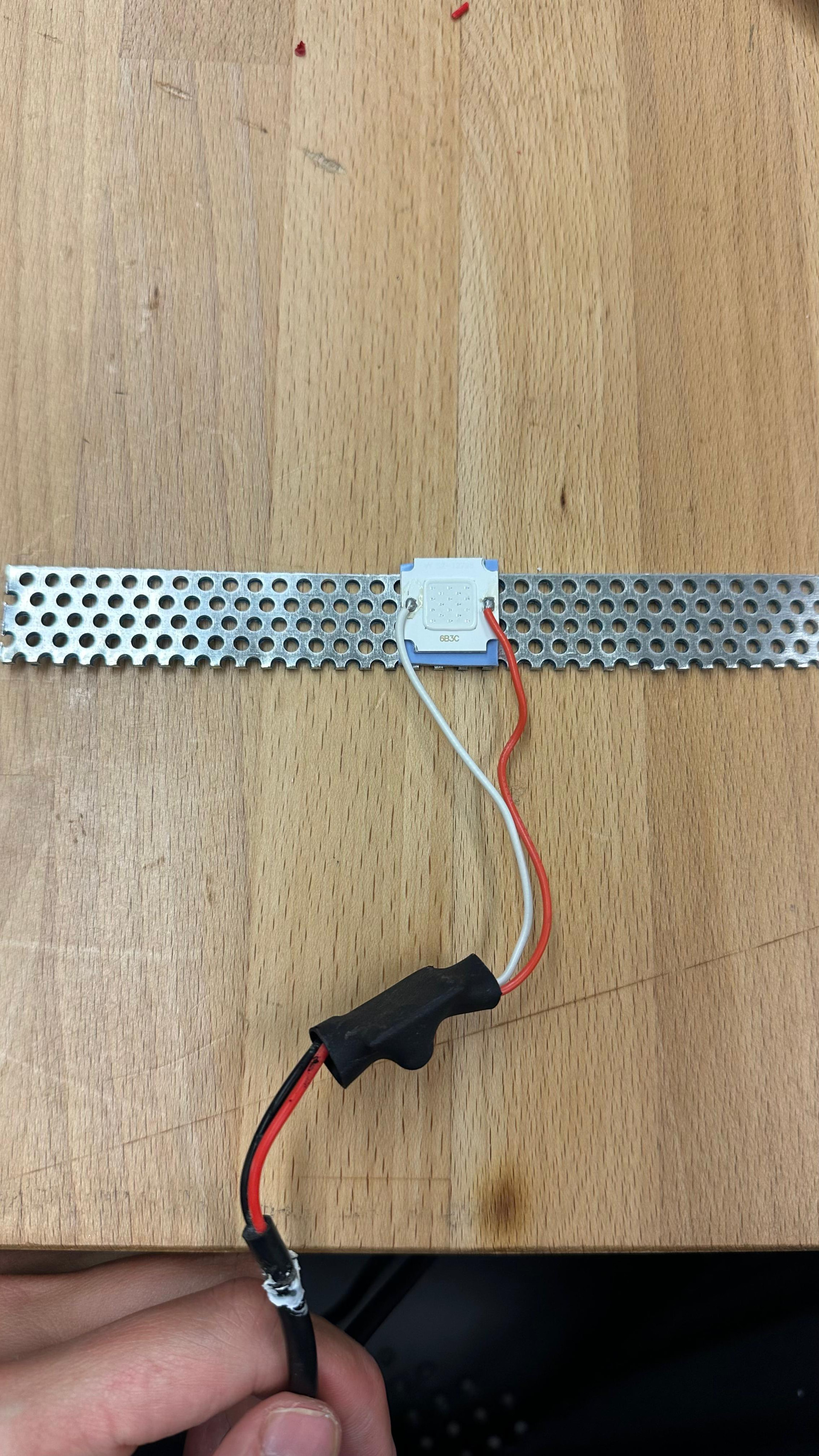
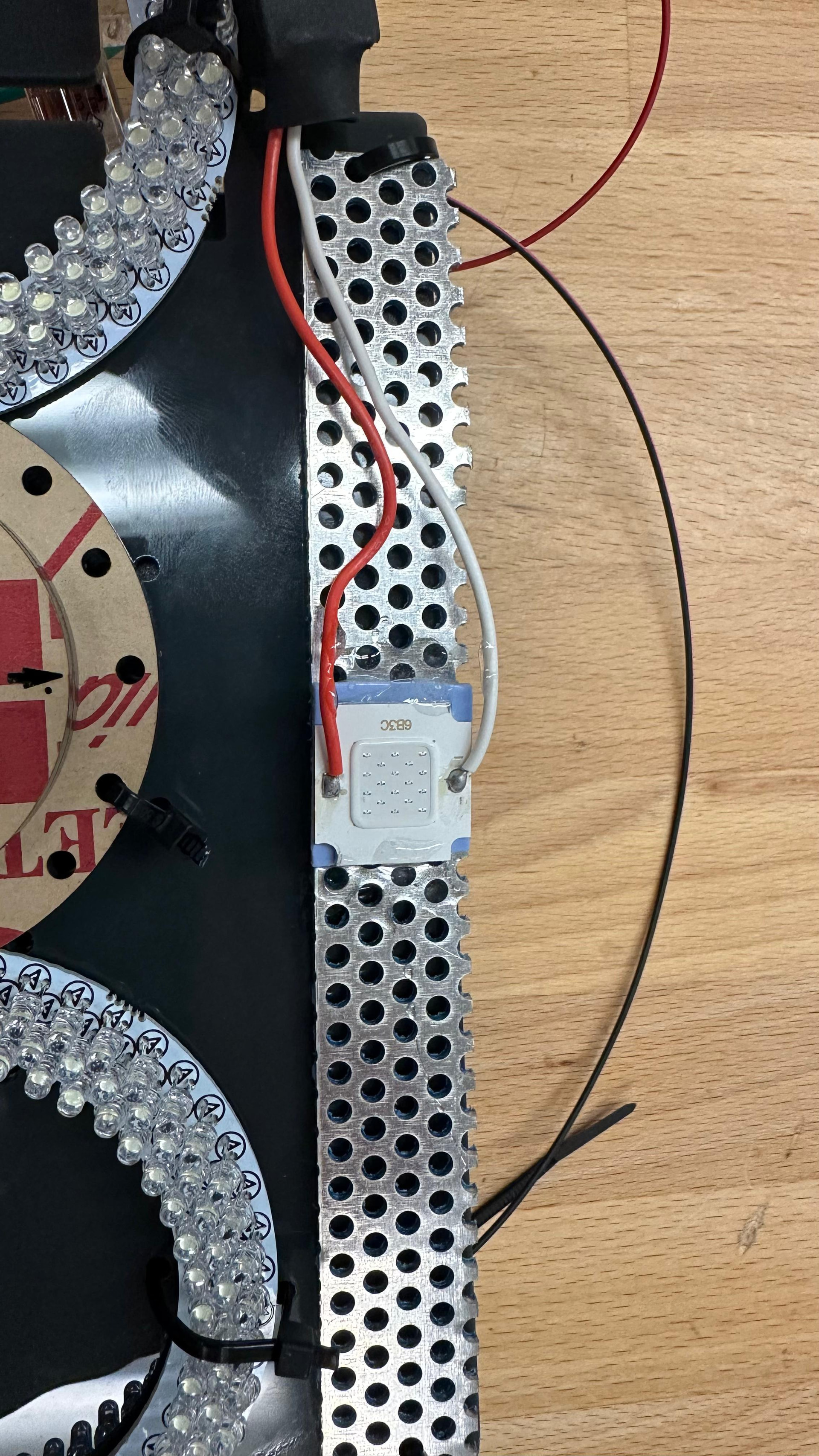
The light was easy to disassemble. After opening it, I removed the light component and attached it to a perforated plate. I used glue to secure the light to the perforated plate.

After mounting the light, I connected the wires again by following the main guideline. This part also worked without any issues, such as cutting the perforated plate etc:

At the end, I attached this piece to the board using zip ties.

Really fantastic documentation so far!

1 Like

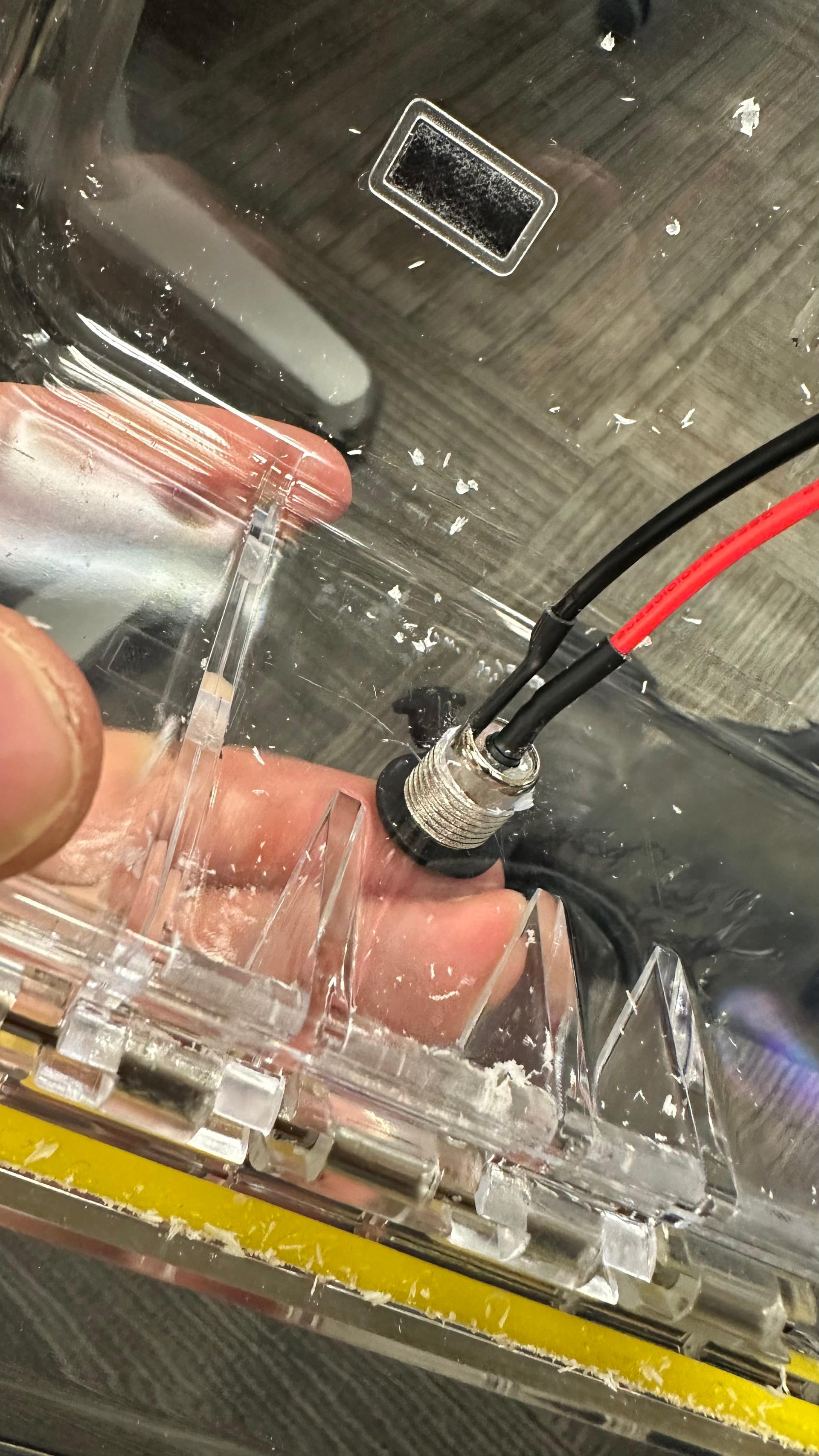
14. Making the Charging Port Hole

Next, I made the hole inside the box for the charging port.

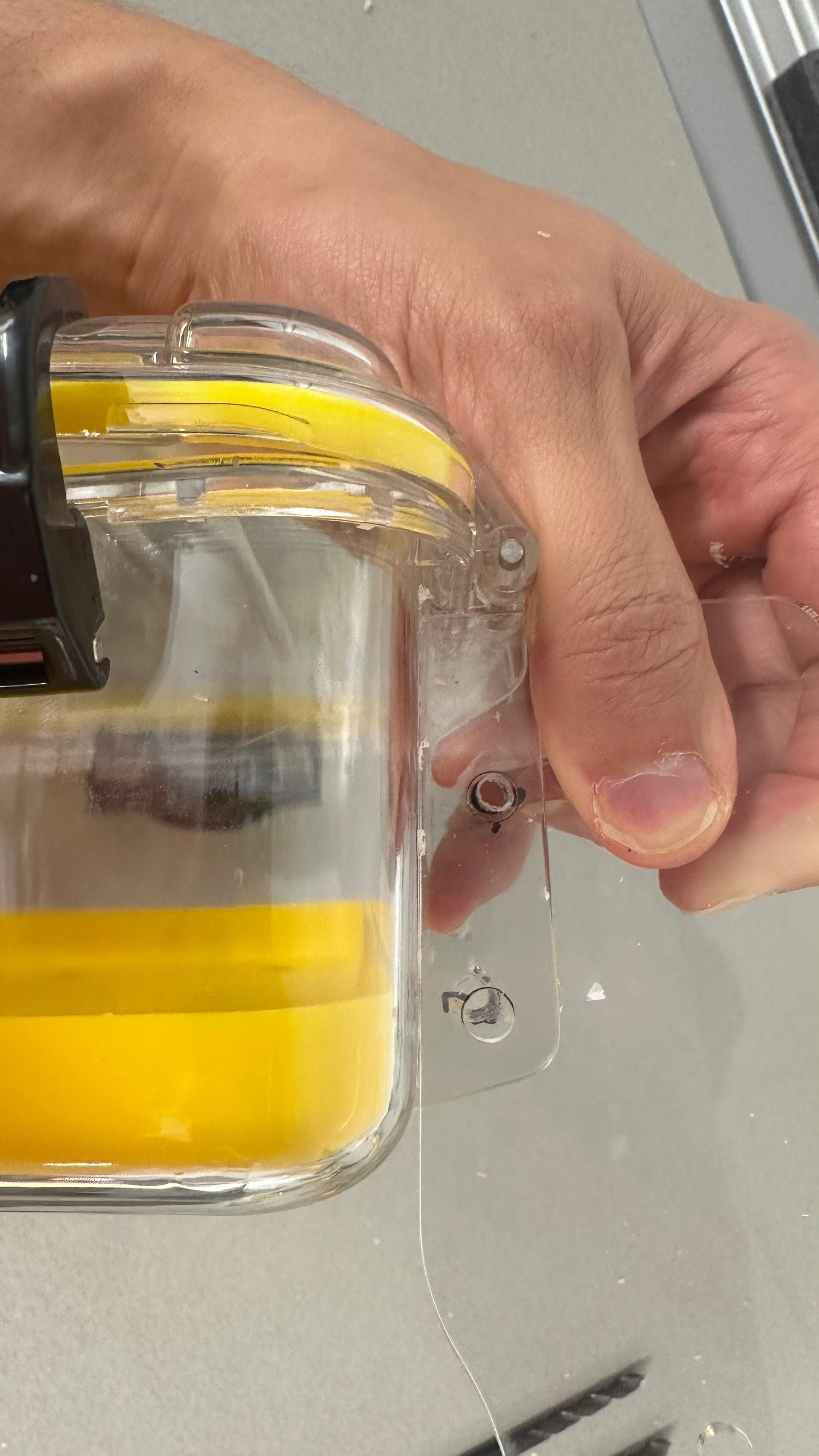
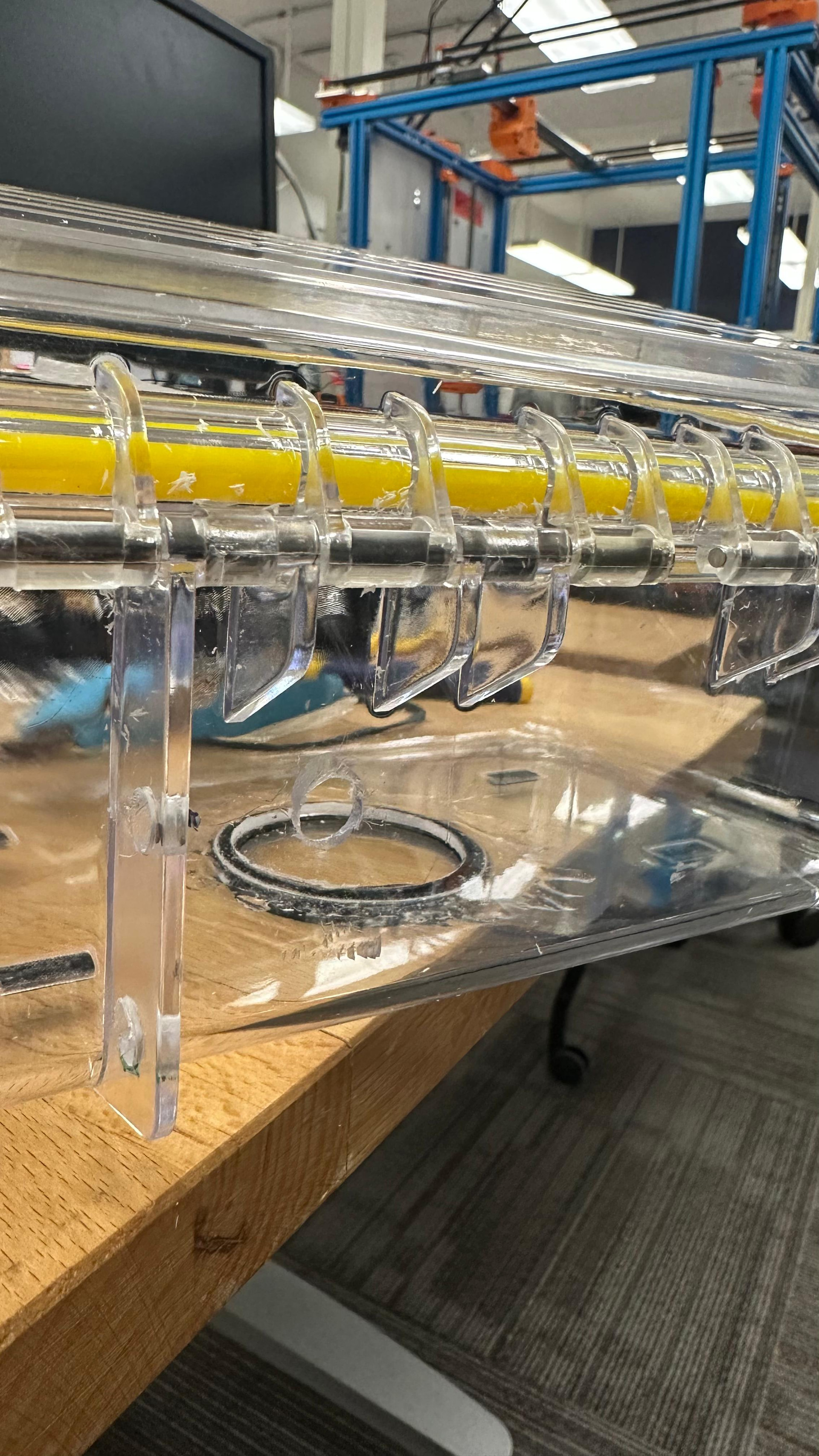
This step was a little tedious because I did not have a large enough drill bit. I had to slowly enlarge the hole and adjust it until the charging port could fit properly.

At the end, I was able to make it work, and the process was straightforward once the hole was large enough.

Also before deciding where to make the hole, place the board inside the box to see where the wires need to come out and make it there.

Test the fit often so the hole does not become too large.

Take your time with this step because the plastic can crack if too much force is used.


15. Completing the Wiring

After making the charging port hole, I completed the wiring.

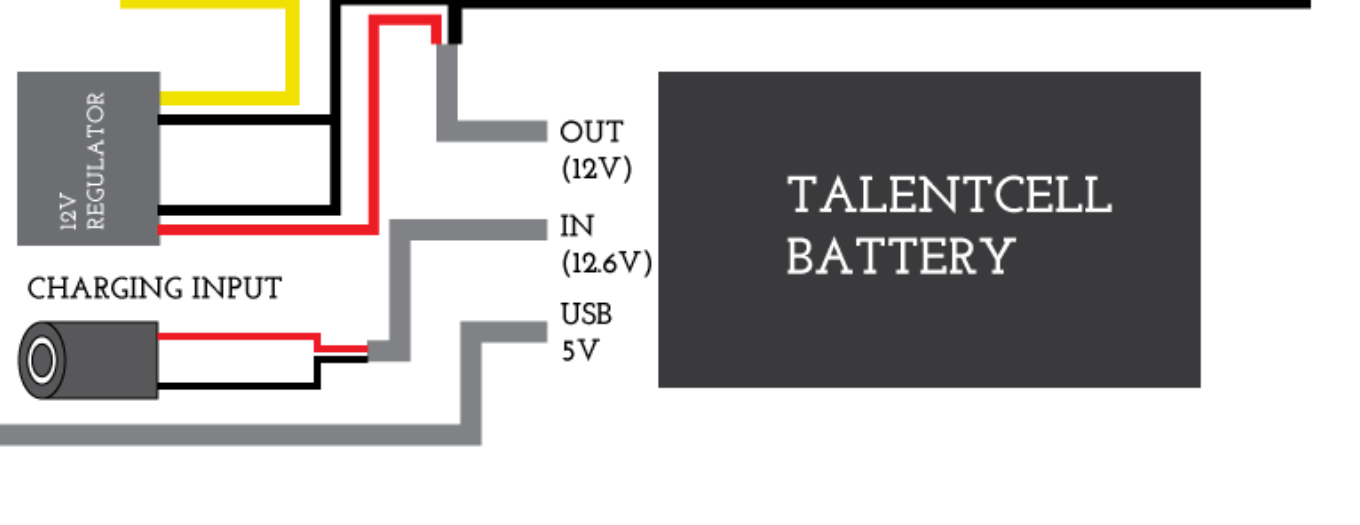
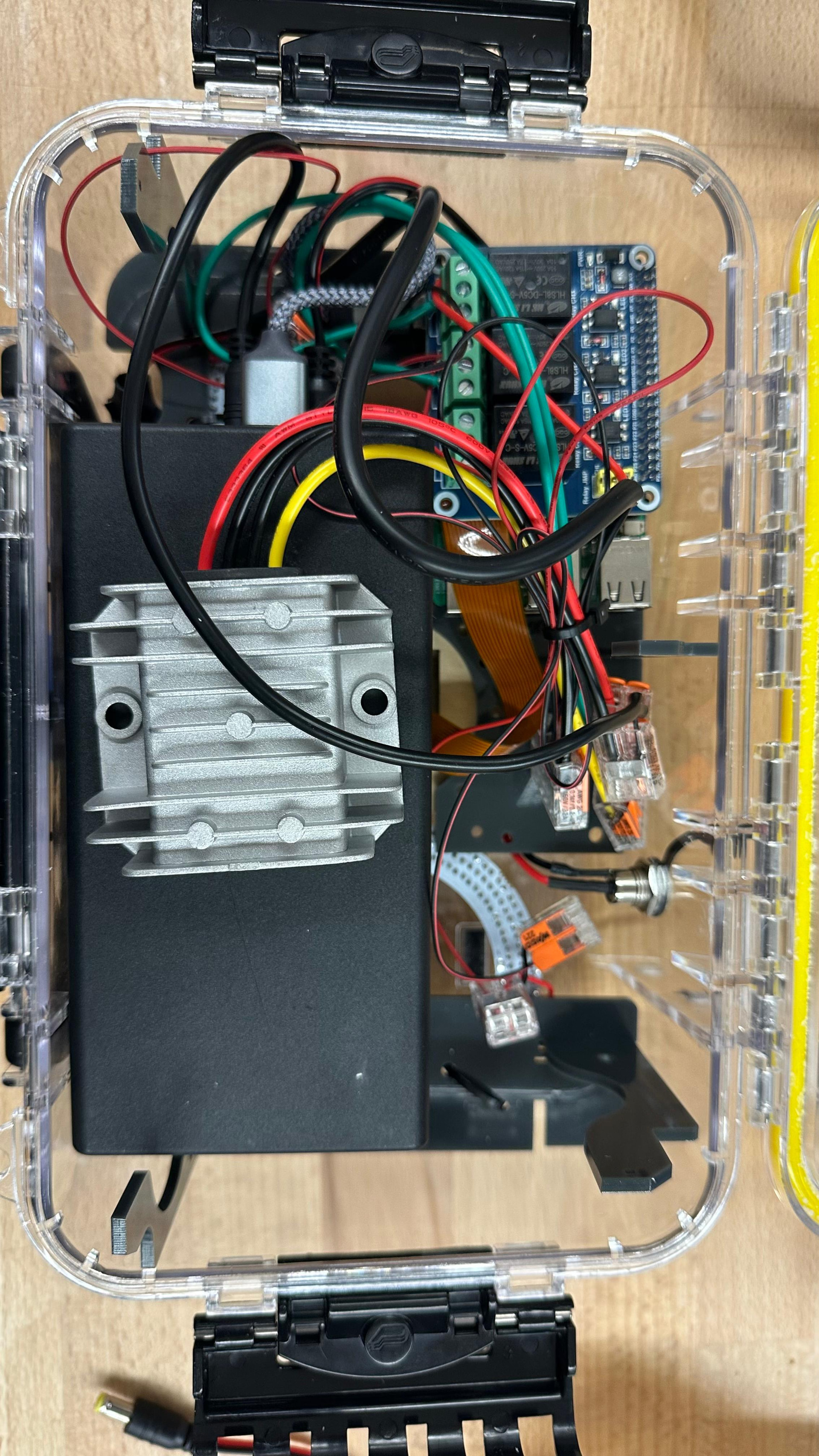
At this stage, I connected all the wires together, including the wires from the battery to the different parts of the system, such as the Raspberry Pi and the other internal components.

The wiring diagram is very important here and should be followed closely. I included the wiring diagram below because it is a must-use reference for this step.

16. Final Assembly and Plastic Arm Issue

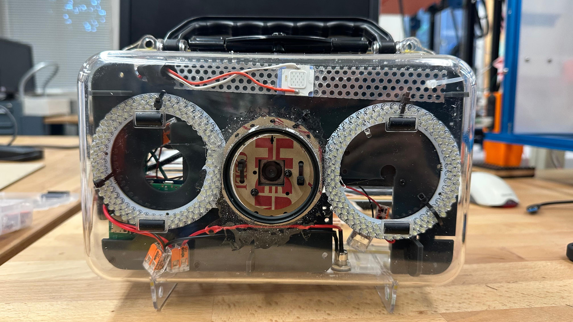
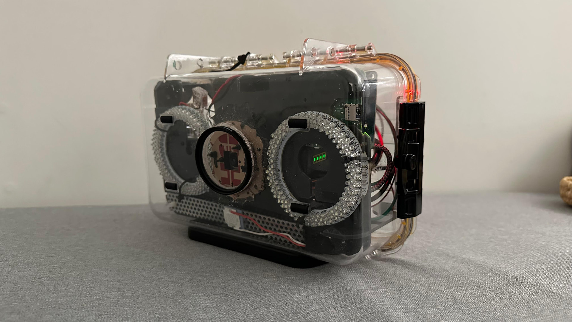
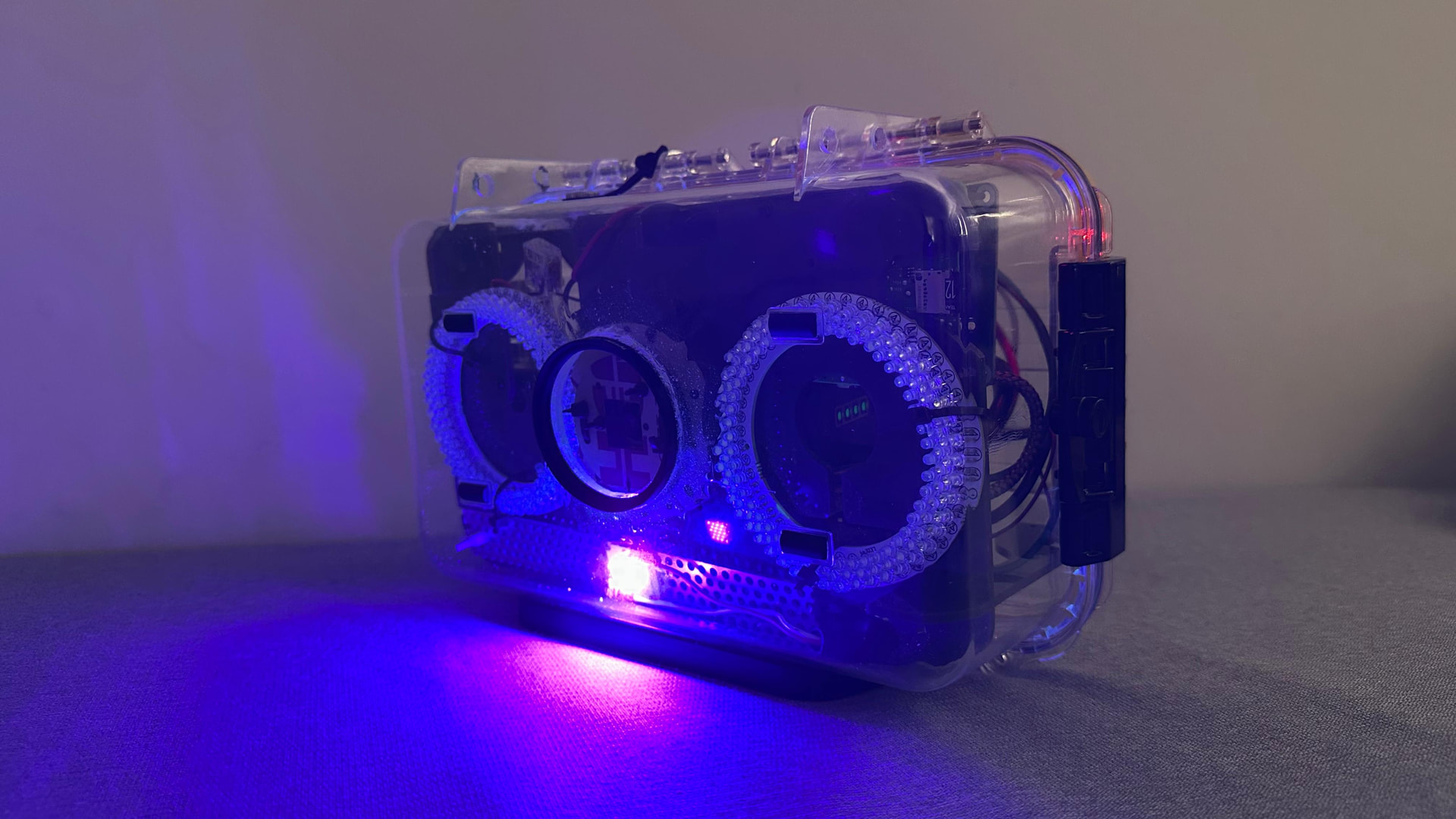
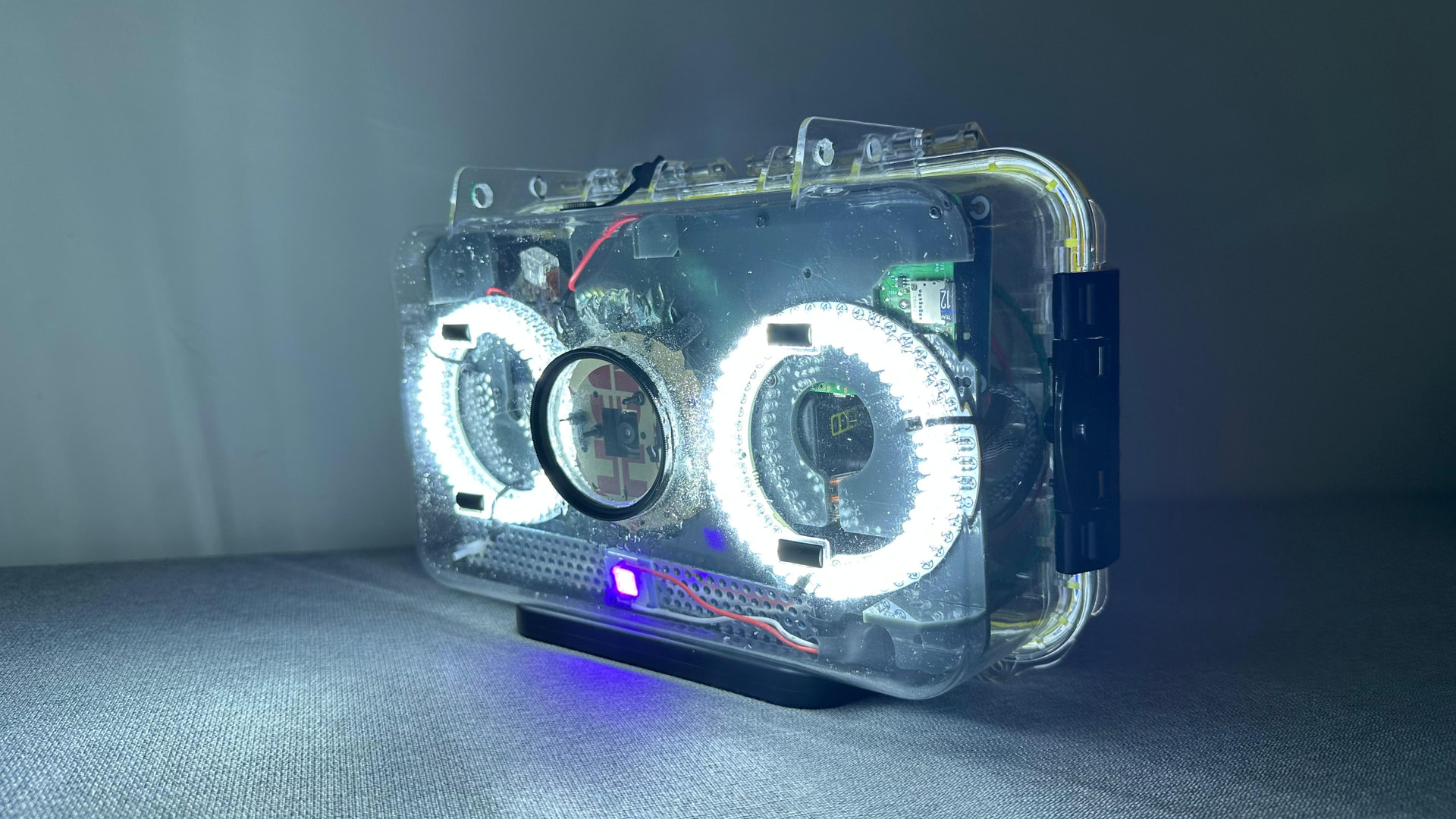
At this point, everything is put together and the Mothbox is ready.

The only issue was with the plastic arms mentioned earlier. One of the thicker pieces had already broken before, and now one of the thinner arms also broke when I tried to fit the Mothbox inside the box.

This showed that the plastic arms can break if even a little extra force is applied, especially during fitting and final assembly.

Because of this, I need to laser cut or print more replacement arms.

Tips:

Be careful when fitting the Mothbox into the box.

Do not force the plastic arms into place.

It is a good idea to laser cut a few extra arms in advance in case any of them break during assembly.

Check the fit gently before doing the final installation.


The Mothbox is now fully assembled and ready for the next step. The next step is testing the system.

1 Like