Hi everyone! Here to look for help with computer vision.
Context
A few folks and and I want to start tinkering with OpenCV, to estimate the pose of a camera relative to a reference pattern on a table (e.g. a QR code).
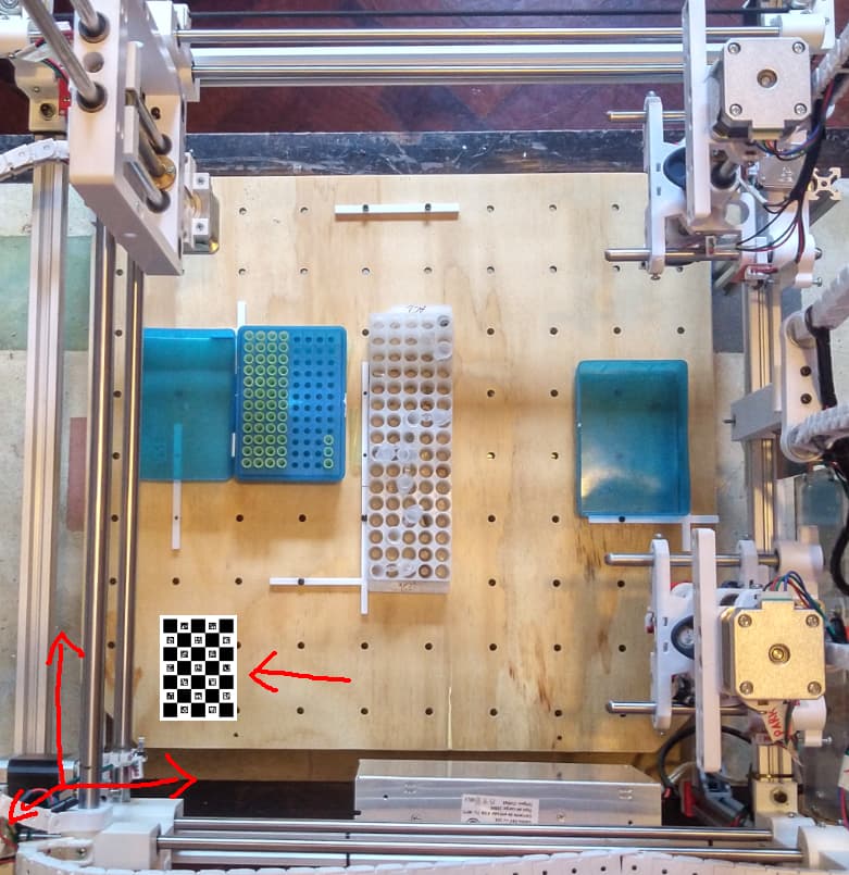
We’d like to use this to get the software of our pipetting robot to auto-calibrate relative to any work surface (e.g. our baseplate, the OT2 deck, or others). Something like this:
It’d be nice to know the position of the robot relative to an arbitrary table/base/deck/etc. The refeernce pattern can look like that QR-ish thing on the bottom-left.
The request
I was wondering if someone around here would be willing to lend a hand, and share their experience with cameras and OpenCV (especially when combined with actuators, maybe like the OFM @julianstirling?).
These are the documents I have so far found, but they’re a bit cryptic to our rookie eyes, and we also would like to know what challenges lie ahead before diving in:
I have not done pose estimation specifically but I have done some computer vision.
Tutorials like this are useful because they demonstrate certain functions but they never quite fit your own situation. Computer vision in my experience is an iterative process.
Start with a single image
Check you can plot your image on your screen
Break down your process into steps (such as finding the chess board) and only tackle step one
Use tutorial to try to tackle step one, looking up the documentation to each function to understand the input arguments
Plot any results possible overlaid on your image. (Lots of plots per image if needed, certainly at least one plot per each function that gives you plotable data)
Once it works for one image, try same method on more images
Once it works for lots of images, repeat the whole process for the second step (starting with one image)
Once the whole system works try with edge cases, or images that shouldn’t work (checking they fail gracefully)
The tutorial gives you a clue of which steps to break it up into and which functions to use.
Nice to hear from you! I am quite happy to see your project turning into a production ready machine.
I have worked with OpenCV quite a bit in my past and generally enjoy to play around with it.
Honestly I am not sure if it is possible, at least with the image provided above. I am particularly skeptic about the demanded precision level of 0.1-0.5 mm.
Just send me some images in full resolution and I will see what my skills can achieve.
I agree this is probably a challenge, but also hoped it is possible for our particular setup. The camera can be relatively close to the patterns, and take multiple pictures.
I’ll send them in a bit. We can meet with @PedroMartinez a project team mate, who is also very interested in learning and working with opencv.
Let me know how this goes and if you need extra hall i can probably get called in. I have a good amount of experience around exactly this.
“We need about 0.1-0.5 mm accuracy from the pose estimation.”
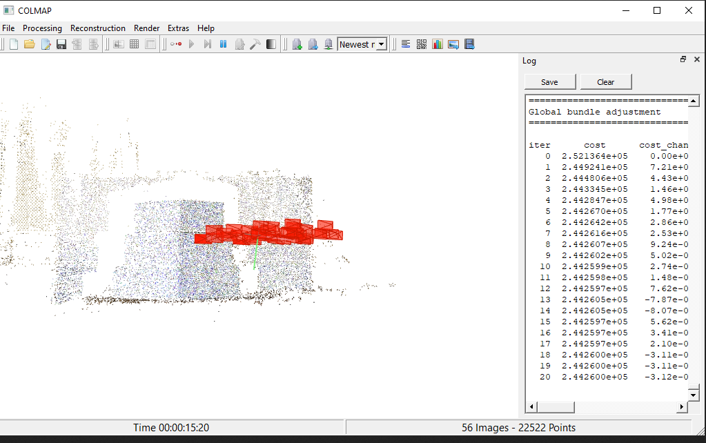
By the way there is a kind of wild new thing where photogrammetry can now provide better camera calibration than checkerboards!
In some projects I do, We used to use checkerboards to calibrate the cameras to get the intrinsic parameters of the lenses. But now we use the open source colmap feed it like 100 pictures and it gives us better camera calibration than nice checkerboard images.
Are the pictures any good as a starting point? For those I used my phone to take pictures similar to the ones we’d get with a camera mounted on the robot. They were totally improvised. Perhaps we should first pick a camera and start from there instead.
I imagine we could use a Raspberry Pi camera, or a widely available USB webcam that is compatible with OpenCV.
Thanks Andy that sounds great! Would you happen to know where we can read about it? (is it this one https://colmap.github.io/ ?)
We’ll probably spend a couple weeks making initial test and then share results.
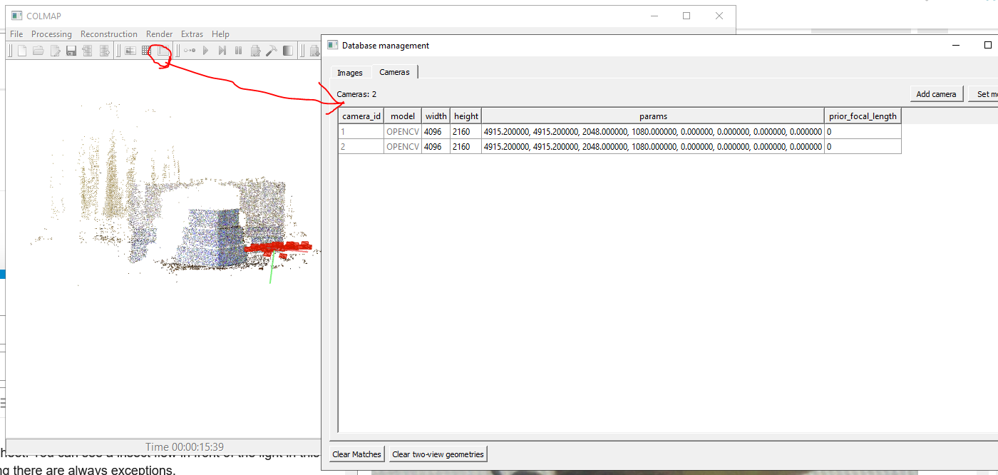
(note these values shown here aren’t actually good calibration values for those cameras, i had messed with a thing and didn’t want to re-compute everything, just wanted to show you how to find those parameters)
I did a quick and dirty calculation using Gimp(image processor) on one of the images(IMG_20230824_133311), the smaller target of 60.45mmx43mm, still results in a cropped image of 873x642, which is about 13pixels/per mm. I didn’t correct for angle, or edges. The Pi Camera HQ Module has a 12.3 megapixel Sony IMX477 sensor, which might be good.
So, IMHO, 0.5mm could be possible, given the 13 pixels/mm to work with, within a reasonable budget(rpi+PiCamera+lense), given the right camera + software setup.
Excellent thanks a lot! I just got my hands on that module (thanks to @ffederici). We just need an appropriate lens for it.
Thanks Andy this is really promising. I’d like to try that out with a regular USB camera, hopefully I won’t need to rely solely on the Pi Camera (or similar).
We’re short on time ATM, so we’ll hopefully have some results to share around October.
I worked extensively with that Charuco board system to do a pose estimation from a webcam. I used it to build part of the manufacturing line that produces and calibrates looking glasses, and I ended up building a special calibration box with a webcam that auto-calibrates the displays. I used python + openCV for the main program, and it worked surprisingly well. It did take me a ridiculously long time to muddle through a bunch of opencv demos and figure out how to do that charuco border alignment and pose estimation.
If you want to talk it over, just email me directly – happy to give you some demo code that worked for me, and talk you through the logic.
Getting high precision from a camera will probably involve calibrating your camera with a checkerboard, and even then you’ll have a limit to your precision based on your resolution, focal depth, and imperfect calibration. I bet you can squeeze more detailed performance from your camera by moving your camera around in a repeatable way (if you can put the camera on an actuator), taking many different images of the same board from different positions, and combining the calculated position from each known location.
Happy to pop on a call and talk it over sometime. Just lmk
but alex, @alex9000 have you tried calibrating a camera yet by just taking 50 photos and tossing em into colmap, it’s awesome! and has given us better calibrations than charuco boards!
In this particular project, we were showing a charuco board on a looking glass screen, and then we needed to estimate the pose of the screen to correct for how it was physically placed in front of the camera. I got really into minimizing the error of the charuco pose estimation, since this would be calibrating every device that came through our factory, and calibrating the camera lens made a small but non-zero improvement in how accurately opencv found the edges of the board.
I only had to do a camera calibration once, because I used the same camera, same distance to the object, same focal range every time, using some an opencv script that pretty much does what you describe–just takes a bunch of photos as you wiggle the camera around in front of a checkerboard, and that generated a calibration. Using no checkerboard+ colmap is great–the less process, the better!
-a
I discussed this with @naikymen yesterday. He said the robot is now moving and ready to mount a camera and produce some working condition images. That dataset will allow us to start designing a system or training a model.
Another possible solution
I’ve been thinking about a machine learning model to work over this, probably also aimed by some machine vission pre processing tools. Being a more tailored solution, it might provide an optimal balance between code complexity and precission.
What I imagine is something similar to a neural network with hidden layers, a Restricted Boltzman Machine. It would take pictures from different fixed “coordinates” (as perceived by the uncalibrated machine) and have one layer for cropping/reshaping, another to predict a unique object and then the outcome would be the distance to that synthetic last object.
Another alternative is to first use geometrical machine vission tools to correct the images and then a model.