Hello all,
sorry if this is the completely wrong place to ask this question but I am unsure on where in the internet I could get help (I also asked this question on Stack Exchange but did not get an answer). If this is the wrong place, I would also be very thankful for a hint on where to ask this question.
I am currently building a basic spectrometer. The main components are an entrance slit, a concave diffraction grating and a CCD sensor (also the other electronics). Since I am on a very tight budget I bought a used diffraction grating online and now I am trying to figure out the needed dimensions of the device. The grating came with a datasheet (Horiba - 532 00 570) but it only specifies:
- groove density = 1200 1/mm
- spectral range = 350 - 850 nm
- blaze wavelength = 450 nm
- dimension 42.4××42.4 mm
On their site they say that the grating is actually designed for a monochromator but I read that that it should also work with a CCD sensor (if tilted correctly). I already contacted Horiba and they only sent me the data sheet which I already have.
How do I find out which distance has to be between entrance and grating, grating and the sensor, what angle should be used between the two arms, as well as the tilt of the sensor in respect with the diffracted beam? I experimented quite a bit and have a setup that works (meaning I have a focused spectral line on the sensor which still fits on it), but I would like to be more precise.
Hi @knicklicht,
Welcome to the GOSH community. I think when they say it is designed “for a monochromator”, they mean that it is designed to be used as one. If you shine while light at it it will diffract the beam into a spectrum, if you had an output slit instead of a CCD you will have monochromatic light.
In answer to your other questions about distances, it depends a lot on your CCD, both the total size and the pixel size, and also if you have any focusing optics except for the fact the grating is concave.
The way I think about a basic spectrometer is to imagine a camera and a slit and nothing else. The further the slit is from the camera, the smaller it will look, you want the slit to be clear on the camera, but not much more than a pixel across. Now if you put a permissive grating in the way some of the beam will be diffracted. If my lens and CCD is big enough I will get spectra either side of the image of the slit. If these spectrum of the incident light has discrete lines, these will be at least as thick as the image of the slit (This is why we wanted the slit to be about a pixel). The further the diffraction grating is from the camera, the wider the spectrum is spread out, this probably means you need to move the rotate the camera a few degrees about the the position of the detector. As the spectrum is now more spread out you have better resolution in frequency (up to a limit determined by other factors). This can all be done with a bit of trial and error.
Now if your diffraction grating is concave you can put the camera at the focal point of the grating, and then experiment with different distances to the slit. Shine the spectrometer at a fluorescent light bulb to get a spectrum with discrete lines. If the lines are really thick you can move the slit further away. If your spectrum is not spread out enough or is too spread out, you will need focusing or de-focusing optics (either lenses or mirrors).
Another option would be to mount the diffraction grating on a geared down stepper motor, and have an output slit before the CCD, this way you would scan through the wavelengths and record the total light on the CCD at each.
Not sure how helpful this is. There often is not a single easy answer. A lot of it depends on what you want to measure, and the resolution you need, the size of the slit, etc.
hoi zäme,
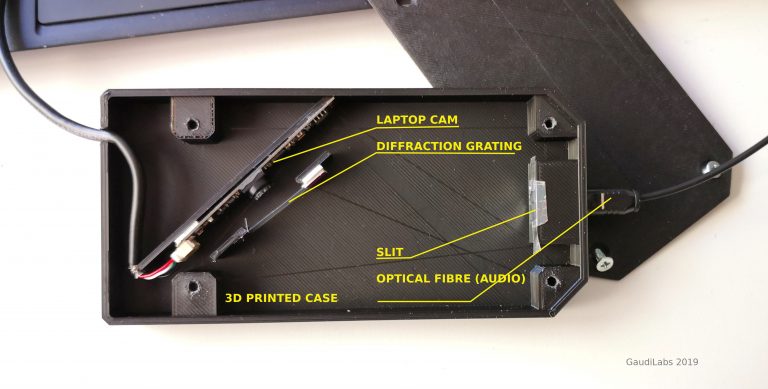
we have also just designed a new spectrometer, with optical fibre connection, which makes it easier to connect to different setups. see some notes here:
https://www.hackteria.org/wiki/DIY_spectroscopy#GaudiLabs_.22Open_Fiber_Spectrometer.22
our goal was “ultra cheap” but useful. standard low.cost webcam HM1355. @gaudi has also written a new software in processing to analyze and do background substraction and other math with it.
as @julianstirling has written, in the end you just gotta try out and test the setup, and then somehow reproducibly make more versions, this is were digital fabrication comes in handy.
in the end, the succes of your experiments relies much more on your research question, sample preparation, quality of the slit, light source, other parts of the setup, than the position of the grating.
i ordered ultra cheap gratings from ali-express. but only found 600 lines / mm, and somehow the rainbow is a bit too small in the current setup.
we are still a bit confused on how to get quantitative measurements from the webcam histogram. are the “brightnessses” that we read linear? how to calibrate intensities? how much into the IR or UV do we really measure something useful?
the spectral calibration is relatively easy using fluorescent light bulps with know emission bands.
1 Like
If you stick duct tape to the back of a cheap CD-R then chop out a section near the edge. Then peel off the duct tape it should peel off the shiny layer leaving you with a diffraction grating. How well it peels off depends on the brand of the CD-R
Thanks a lot for the replies. The posts had new information that I did not know (or had not thought about). First of all I will now place my sensor at the focal point of the concave grating. I will also use the florescent light source to generate a spectrum with distinct lines to assess the setup. @julianstirling, pointing out the simple working mechanism helped a lot. Am I right that given, that the sensor is in the focal point (where I would get the highest intensity) I need to make sure that the portion of the spectrum that I am interested in (VIS) fits on the sensor and if it does not, that I need to compromise between intensity and spectral range? I do not intend to use any other optical elements.
@dusjagr, I like your idea of using a toslink optical fiber. That should work well for my purposes.