I was wondering if anyone here is working on things related to Harmful Algal Bloom. I saw it mentioned in this post but don’t see it mentioned anywhere else. I don’t have anything specific to discuss, I’m just interested in hearing from any of you working in this area.
Hi All,
I wrote some articles on Diatoms a type of Algae that can out compete harmful Algae if they have sufficient Silicon.
https://www.linkedin.com/pulse/regenerative-alternatives-burgeoning-carbon-capture-storage-merlo/
A Citizen Science project on the role of Silicon.
https://docs.google.com/document/d/18PQbwGT2k3fooYPqh8d_dZjPH7Ue8iaaJvZjGoXGlxI/edit
Cheers
D. Bruce Merlo
514 462-4298
I did, a long time ago. The AUV I showed off during Shenzhen was more generally to monitor water quality, but the ultimate goal was to detect chlorophyll a over a large area, which is a proxy for the amount of algae present.
This project ultimately got shelved due to lack of a testing/proving area, ideally a convenient small freshwater lake. The AUV was very low cost, so restarting the project does not require much/any direct funding. The testing area remains key. If anyone is interested in taking this on, I’d be glad to provide more details.
Thanks for the reply @Bruce . The Vesta Project linked in the articles seemed to have good backing and involvement, but there hasn’t been a blog post or podcast since 2022. Is that project still going?
I don’t see any sensors or measurement capability for the Citizen Science project to measure the effect. Did I overlook it, or is the focus on the recipe and the science behind it instead of measurement?
Thanks @Harold
When you say “small freshwater lake”, what is “small” (area, max/min depth, etc)? Is frequent access required, or is it just a matter of completing a few sample runs with the AUV?
Is the hardware of the AUV documented anywhere?
Hi Jeremy,
The lake should be swimming pool deep, as the depth is needed for the AUV to initiate a dive.
The testing (and development) is of the navigation system, so the lake needs to be say 200+m at its longest. After this, the next stage of the navigation needs to account for current, so this will take place in salt water, the final goal! A chase boat will be needed here, at least a kayak, which is what I have used in that video.
Another aspect of development not yet addressed is the chlorophyll a sensor. Commercial units cost around USD1000, which dwarfs the cost of the rest of the vehicle. At the time there were a few papers on open sensors, but these were more proof of concept. I have not kept up in this area, but it is terribly interesting.
I should mention that the state of technology has moved so much in the last years that an overhaul makes sense. For instance, the processor was a lowly 328p, and much better GPS units are available now. The CTD never did work properly and will need attention. The propulsion and attitude control are solid.
The repo such as it is, is here. I wrote an article about it for the IEEE newsletter (page 50). The IEEE archives lost a large swathe of content so this is a copy I had saved.
That’s a very clever propulsion/control mechanism on the AUV. I have a few questions after looking at the repo.
- The DXF files in the repository have drawings but no dimensions. Is FreeCAD dropping the dimensions layer somehow during import?
- It doesn’t look like there are any 3D models (STEP or otherwise). Is that correct?
- I’m assuming the machined PVC parts could be 3D printed in something like PETG, correct?
Is something like this what you would be looking for to detect chlorophyll? There’s an Arduino forum link in that post where people are discussing how it could be done.
By opening in LibreCAD I was able to answer question #1. Dimensions and notations are present in baby.dxf. I think the data is also there to get dimensions from antenna.dxf and tracker.dxf, even though dimensions haven’t been added yet.
Hi Jeremy,
Sorry for the late reply. There’s no 3D model; the CAD output required was 2D blueprints for the machinist (usually me) so no 3D outputs were needed. Parts were machined or made by hand or were CNC routed. Some Al parts were brazed assemblies. In some places the PCB also served a structural function. 3D printing was not employed.
Most parts were made of aluminium. The hull was 3-1/2" stock Al pipe and the bulkheads were from 1/2" Al bar. The crush depth is something like 400m which might be useful even if the mission involves chlorophyll a. (This kind of AUV is most useful for multi-day missions, which would involve sleeping on the seabed of unknown depth between readings so it does not drift.) At any rate, ballast is always needed, and while using PVC could make manufacture easier, it would make buoyancy trimming more difficult. Nonetheless, PVC construction is useful in waters where a collision with boat traffic is possible. In which case it is better that the AUV be sacrificed than have a jet skier break his neck.
Yes that is the paper I recall, or one very similar. Instead of using an expensive Hamamatsu photodiode, it may be possible to substitute a red LED of the appropriate wavelength. These behave like wavelength-specific photodiodes, so the red filter can be dispensed with. The downside is that LEDs are not characterised for off label use, so calibration will be needed. However this is a known and used legit approach.
The antennas’ radome design was constantly in flux, but the general idea was to place the helical 433 MHz comms antenna (it looks like a spring) at the tip, and have the GPS antenna just below it. The shaft was a stiff nylon pneumatic hose, straightened under heat. Initially the GPS antenna was a passive chip, very small, but it became obvious that there was not enough gain. I tried adding a homebrew LNA, but that was problematic and undebuggable. My thinking now is that a small active patch antenna is needed, and these are now cheap and easily available and I’m using them for a different project.
It was mentioned in the article that the Baby AUV has payload space. Am I correct in assuming that it should be possible to add the chlorophyll a sensor and maybe a pH sensor to have the AUV patrol for Harmful Algal Blooms?
Hi Jeremy,
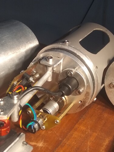
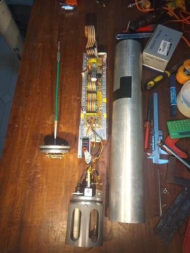
Yes, the end goal was to also carry a chlorophyll a sensor. I’m not sure about a pH sensor as well, you can judge from the photo the amount of space available on the bulkhead, which is the bottleneck. Possibly you could ditch the conductivity sensor in favour of pH.
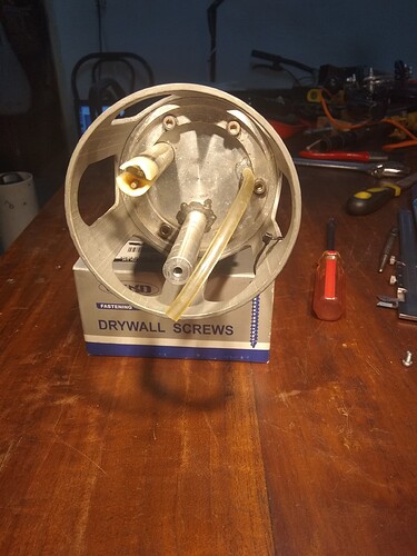
(Conductivity probe (with thermistor) at 10 o’clock, propeller shaft at 6 o’clock, and the tube connects to the depth sensor.)
(Rear bulkhead from the inside. It’s pretty busy in there.)
(Circuit boards are hiding under the ribbon cable. These can be stacked to make more space.)
@Harold Is there a BOM (Bill of Materials) anywhere? I do not see one in the repository. Specifically, the nipple for the depth tube looks off-the-shelf, but it is not called out on the drawing. Also, it sounds like the neoprene used in the expansion seals is not available anymore, but the shape, size, etc is not spec’d anywhere that I can see so that an alternative can be sourced.
Hi Jeremy,
Sorry, the nipple was fait maison. To save bulkhead real estate, it had to be brazed in rather than screwed in. The dimensions are not critical, the barbed fitting on the pressure sensor can be used as a model. The purpose of the PVC tube extension is to protect the MPX5700 pressure sensor from water level rising to meet the sensor. The tube also makes it easy to test the sensor by means of a slip tip syringe.
HOWEVER, arguably a better sensor is the MPS5837 but I never got around to integrating it, which seems not straightforward.
The neoprene seals were sourced from a hole in the wall shop, no part number, no idea what the original intended use was. Practically speaking, anything with 20 Shore A hardness or thereabouts will be ok. Neoprene is nice because superglue or wet suit repair glue can be used to make rings from strips. The glued joint will be under compression, so making rings this way is ok. The rings could also be cast in place in silicone or polyurethane. In any case, the rings would be lubed with a smearing of silicone grease on assembly, which involves tightening the 6 screws (these should also be greased for corrosion protection) uniformly and gradually in a star pattern as usual. On tightening, this design regrettably does not bottom out in metal-to-metal contact; you just tighten evenly until the screws feel snug.
If you think this project is worth pursuing, Leslie Birch @zengirl2 and Shannon Hicks @shicks may be interested. I had offered it to David Lang, but he passed.
Thanks @Harold
Was the neoprene in cord or sheet form? Cord like this seems intuitive, but I don’t know.
Hi Jeremy,
I should have mentioned it was solid neoprene, not neoprene foam. I’ve cut the rings from sheet before I found square section strip. Round may work, I haven’t tried it.
Coming to this late, with something probably irrelevant. The traditional method for dealing with algae in mill ponds it to make big sausages from bound up barley straw. Put the straw in the water and after a few weeks it waterlogged and sinks, as it rots away it produces a small amount of mild hydrogen peroxide which limits algal growth.
Maybe we need an open source barley-straw sausage maker!
@julianstirling That’s an interesting idea since the straw is left over from harvesting the Barley anyway. It sounds like it will inhibit all algae growth, with no ability to target harmful algae separpately, but I could be wrong on that (I know nothing about algae).
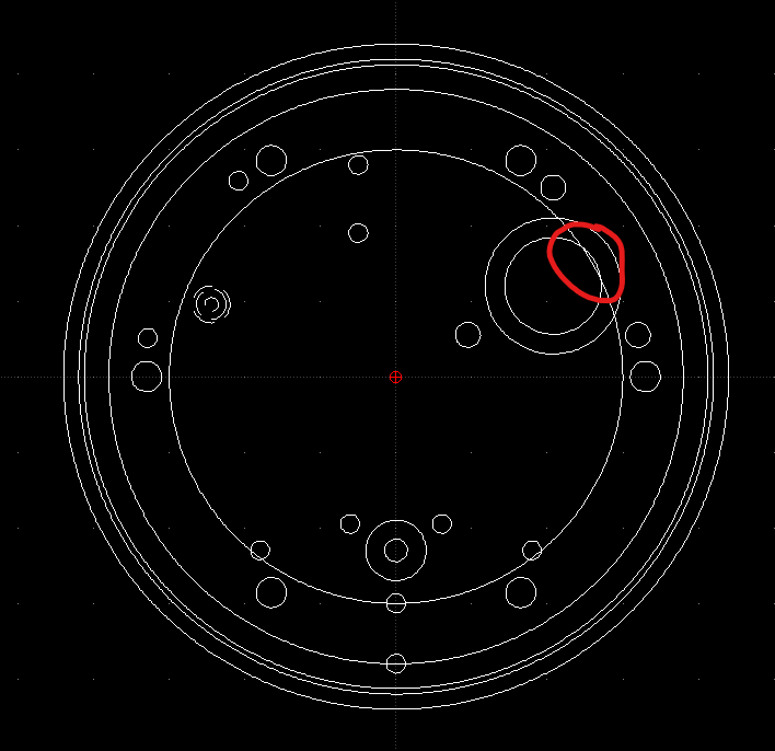
@Harold I see an area of interference in the design, and I wonder if you noticed it before as well. It is the hole that I believe holds the conductivity sensor, and it seems to overlap the inner ring of the rear clamp. I overlaid the rear clamp and the rear end/bulkhead in LibreCAD to show what I mean. Screenshot below.
Is it irrelevant because of how the assembly goes together?
Hi Jeremy,
Sorry for the late reply. A notch was filed by hand into the clamp
ring to address the interference with the EC sensor. It’s possible to
move the sensor, but I had wanted to reserve some space on the
bulkhead for future use, just in case. You won’t need to do this if
you don’t install the EC sensor, which is a Chinese industrial unit,
or use a different one. I could never get this EC unit to work
properly anyway. I know Atlas Scientific have an EC unit for about
USD100 but IIRC it is not intended to be bulkhead mounted, which seems
to me to be terribly important. I spent quite a lot of time on trying
to construct a small EC galvanic cell but the effort did not pay off.
Hi Jeremy,
I haven’t thought about this in a while, but there is another way to seal the end bulkheads. The current compressed rubber method works very well and is robust, but it does take up bulkhead real estate.
The alternative is to use plain old double o-rings in the bulkheads that seal against the hull (the surface finish as-extruded is good enough), and to hold them against the hull using 2 very long shoulder bolts or all-threads going through the front bulkhead (at the 3 and 9 o’clock positions), through the length of the hull, and blind into the rear bulkhead. Naturally a small o-ring would be used to seal the shoulder bolt against the front bulkhead.
The shoulder bolts then also serve to key the innards against movement in the roll sense. At the moment this keying function is performed by the servo arm.
Thanks @Harold
I’m currently just trying to reproduce the design in 3D as-is with smaller fixes, but the design is set up to be parametric, so there could be something like a meta-level seal_type parameter later that reconfigures the AUV end seals. Right now there is only one meta-level use_conductivity_sensor parameter that only adds an extra notch in the rear clamp if that parameter is set to True. Ideally the design would be constructed in a way where a builder could choose from a set of sensors and set the bulkhead seal type, and the AUV design would be configured to use those. However, I’m just doing this as an experimental side project, so I’m not sure that it will ever get to that point.


