Replication team: Starting the OpenFlexure Low-Cost Microscope

Notes on Sourcing Parts in the US

Hi everyone,

I am starting a build of the OpenFlexure low-cost microscope, and I wanted to share my first experience with sourcing parts. I am reproducing an existing open hardware design, so I am following the official OpenFlexure documentation as closely as I can.

The main project page and bill of materials I am working from is:

Official OpenFlexure Low-Cost Microscope BOM

The project is from the OpenFlexure Community, and the goal is to build the low-cost OpenFlexure microscope.

The first step for me was not printing or assembling the microscope. The first real step was going through the bill of materials and trying to find all the parts. This took a lot more time than I expected.

A lot of the suggested parts seem to be easier to source from UK vendors or international suppliers. Some parts are also available through Alibaba, AliExpress, or similar websites. That can work, but for someone building this in the US, it becomes more difficult. Shipping times can be long, some parts are not easy to match exactly, and some US suppliers sell parts in large quantities, so you end up buying many extra parts you do not need.

I tried to find similar or matching parts from US-based sources where possible. These are the links I found so far:

Main OpenFlexure documentation

Possible hardware and material sources

Possible electronics and wiring sources

Parts still needed separately

The official BOM also requires a Raspberry Pi and power supply. These still need to be ordered separately:

  • Raspberry Pi 4 Model B, 4 GB RAM

  • Raspberry Pi power supply, 5.1 V 3 A with USB-C

The main issue I am seeing is that the total cost becomes higher than expected. It is not only the price of each part. It is also the shipping, the wait time, and the fact that many parts are sold in packs. So I may need only a few screws, nuts, washers, or connectors, but I have to buy a full package. That leaves me with many extra parts that I probably will not use.

Another issue is that some parts are not fully available in the US, or they are not easy to match exactly. Ordering from abroad is possible, but it can take a long time. Because of that, I am not sure yet how practical it is to source every part one by one.

Because of this, I also found another option:

IO Rodeo OpenFlexure Microscope Kit

This kit seems to include most of the parts needed for the OpenFlexure Microscope v7. From the product page, it includes the 3D-printed parts, Raspberry Pi Camera Board v2, Sangaboard v0.5, three 28BYJ-48 stepper motors, a microSD card, condenser lens, light oil, illumination kit, Allen key, and the hardware kit.

The important point is that the Raspberry Pi and the Raspberry Pi power supply are still not included. Those still need to be purchased separately.

I have not ordered from IO Rodeo yet, so I cannot comment on shipping speed or the full buying experience. But at this stage, the kit looks like it may be the better path for a US-based build. It may save time, reduce mistakes, and avoid buying many extra parts from different suppliers.

My takeaway so far is that the OpenFlexure microscope is a great open hardware project, but sourcing the parts is a major part of the build. For someone in the US, ordering everything one by one may be possible, but it takes a lot of time and may not be the cheapest option after shipping and extra quantities are included.

I am still deciding whether to continue sourcing the parts myself or order the IO Rodeo kit and then only buy the Raspberry Pi and power supply separately.

I wanted to share this early step because it may help other people who are also trying to build the OpenFlexure low-cost microscope in the US.
1 Like

One of my undergrads assembled IORodeo’s OpenFlexure Microscope a few months ago. I placed an order for another one on Saturday, and as I remember, I was able to order the Raspberry Pi from them. The IORodeo people are in the GOSH forum. They ought to get your message.

4 Likes

It’s great you found the IO Rodeo team! Our system is working!!!

it’s a good philosophical question for this replication project about buying the kit vs building and sourcing from scratch. i’ll have a think about what we should aim for for now!

I have recently built the high resolution Openflexure (from a kit) and two of the manual Openflexures (no kit). I sympathise with you on sourcing components, although I am based in the UK.

I would really recommend the Manual Openflexure over the motorised models. I do not find the motors to be very useful and they significantly add to the complexity. The manual design also makes use of a modified webcam for imaging which means you don’t need a Raspberry pi. I think this is a significant advantage in the current climate where Raspberry pis are so expensive (and I think something many of these open hardware projects will need to adapt to going forward). I then used a cheap microcontroller to run an LED with a resistor for the illumination

Some other thoughts on sourcing the components:

A lot of the bits you are going to have spares of are just M3 bolts and screws which are very cheap and useable for many things. If you are looking for an O-ring substitute, I think an elastic band (original design used these) would be fine.

Lenses are a bit tricky to source. I did manage to get cheap LED lenses (from amazon) for the condenser. The modified webcam works great here as you can use its lens as the microscope objective.

1 Like

Thank you all for your comments.

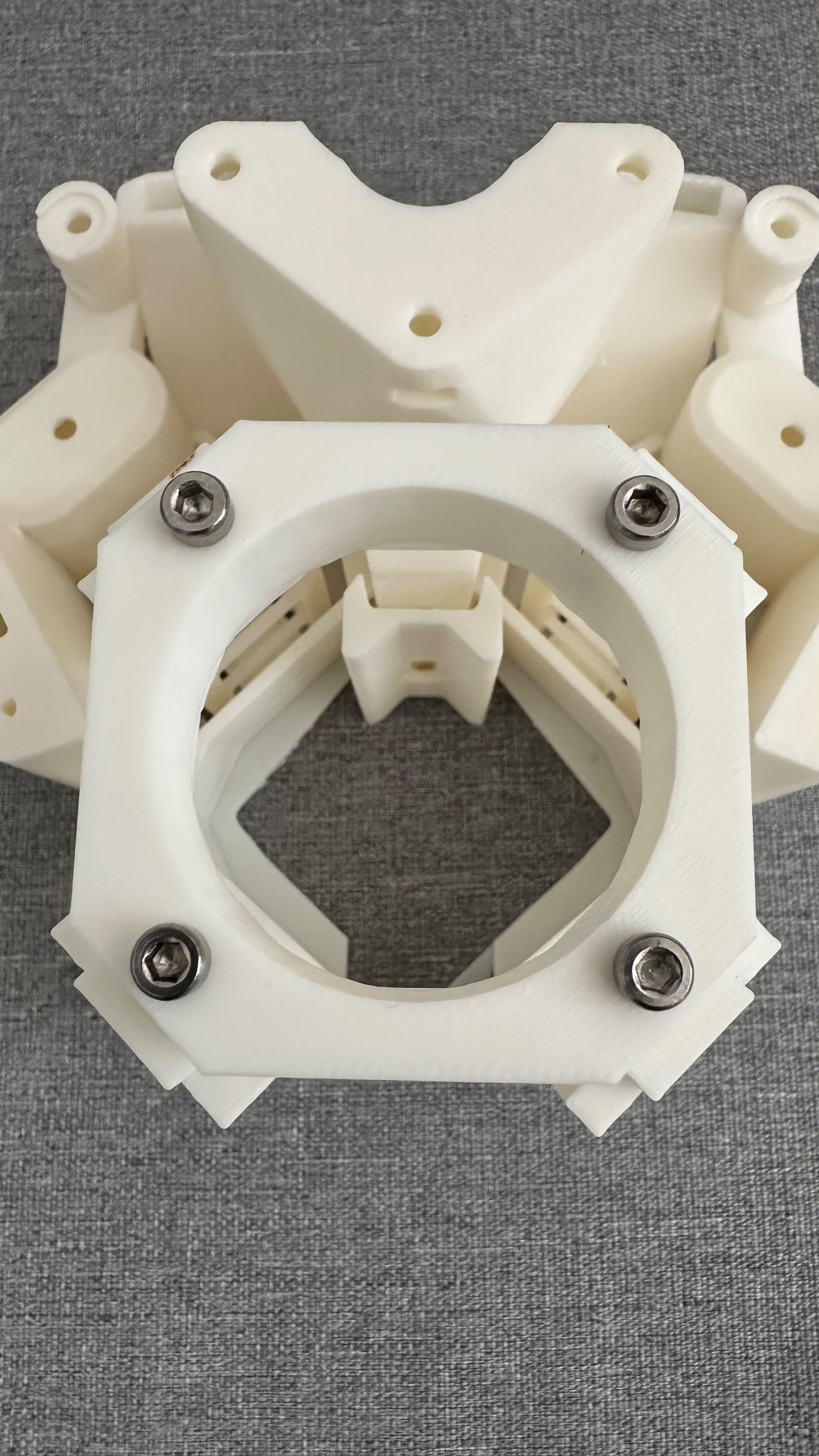
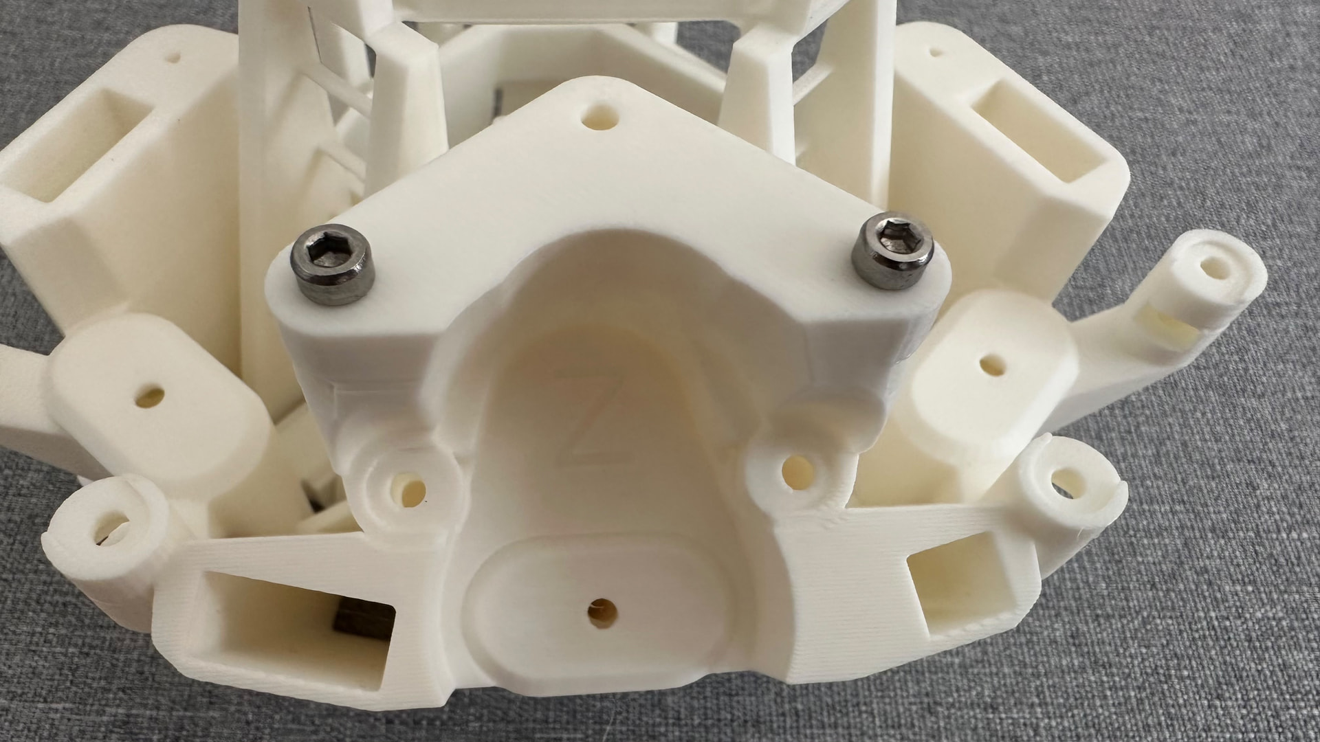
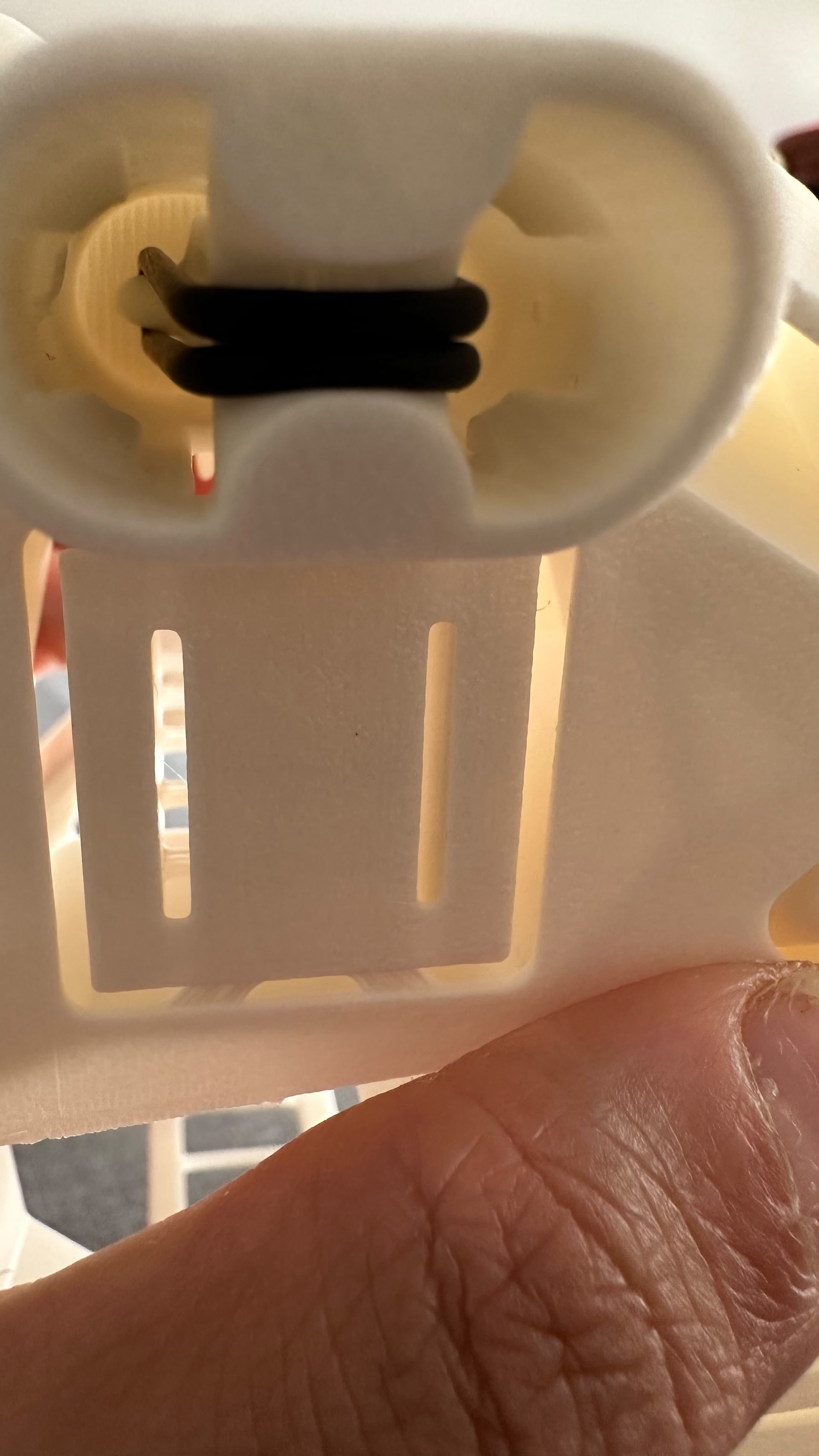
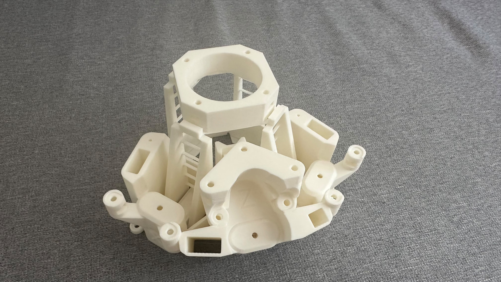
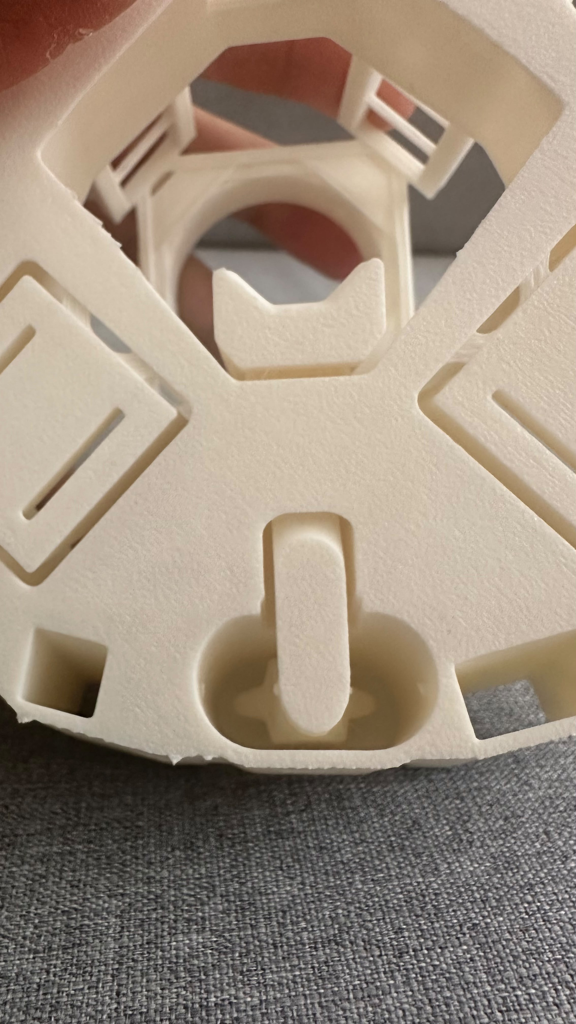
First, I prepared the 3D-printed parts by carefully removing the support material. Some of the internal features are thin and can break easily, so take your time. I may have broken a small internal part while removing the supports. See the image below.

Next, I installed the M3 × 10 mm socket-head screws and nuts. This part can be a little tedious. Place each nut into its small slot, insert the screw, and tighten it while holding the nut in place. Repeat the same process for the two screws and nuts on the other side.

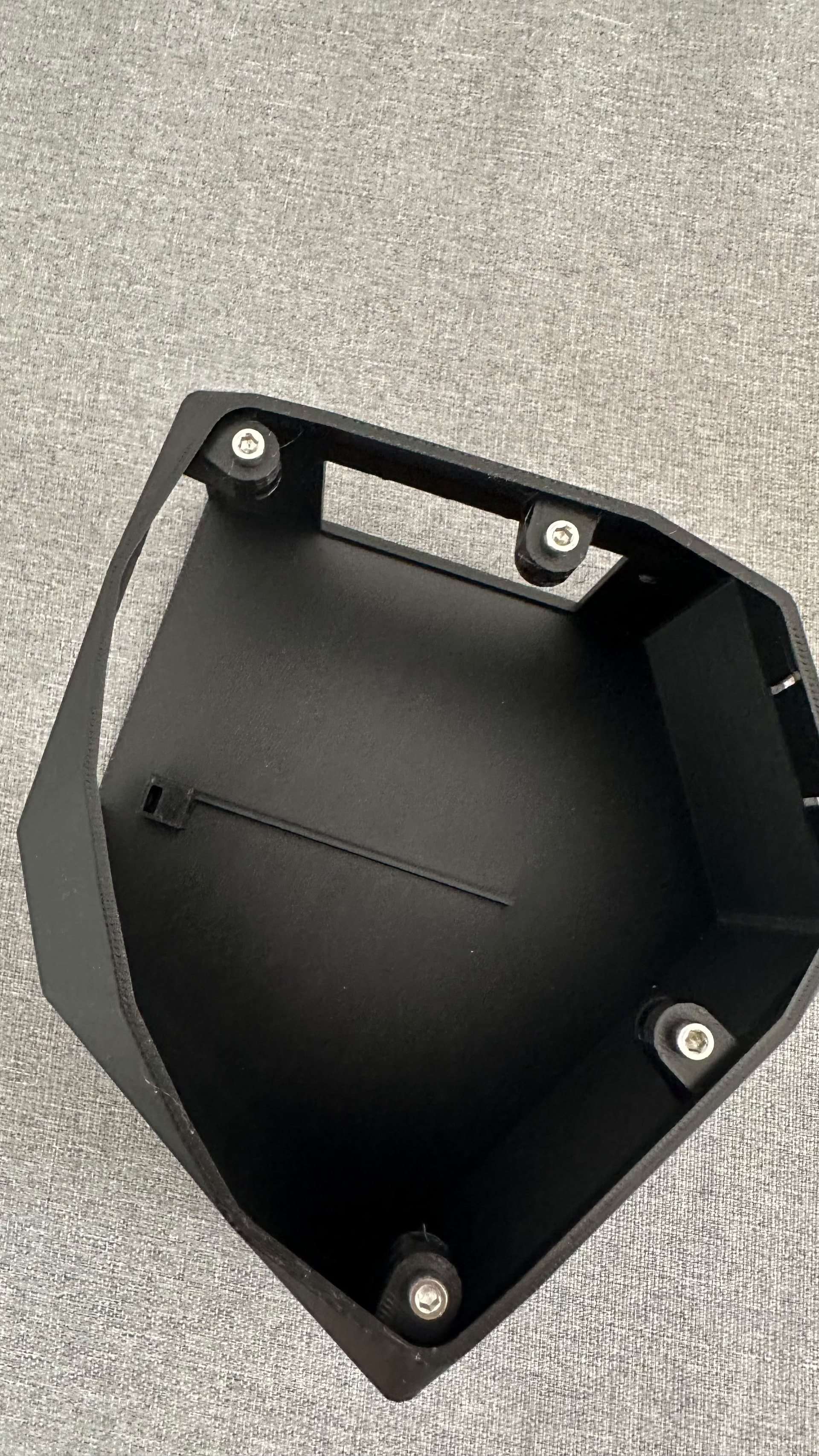
Follow the same process for the microscope stand, as shown below.

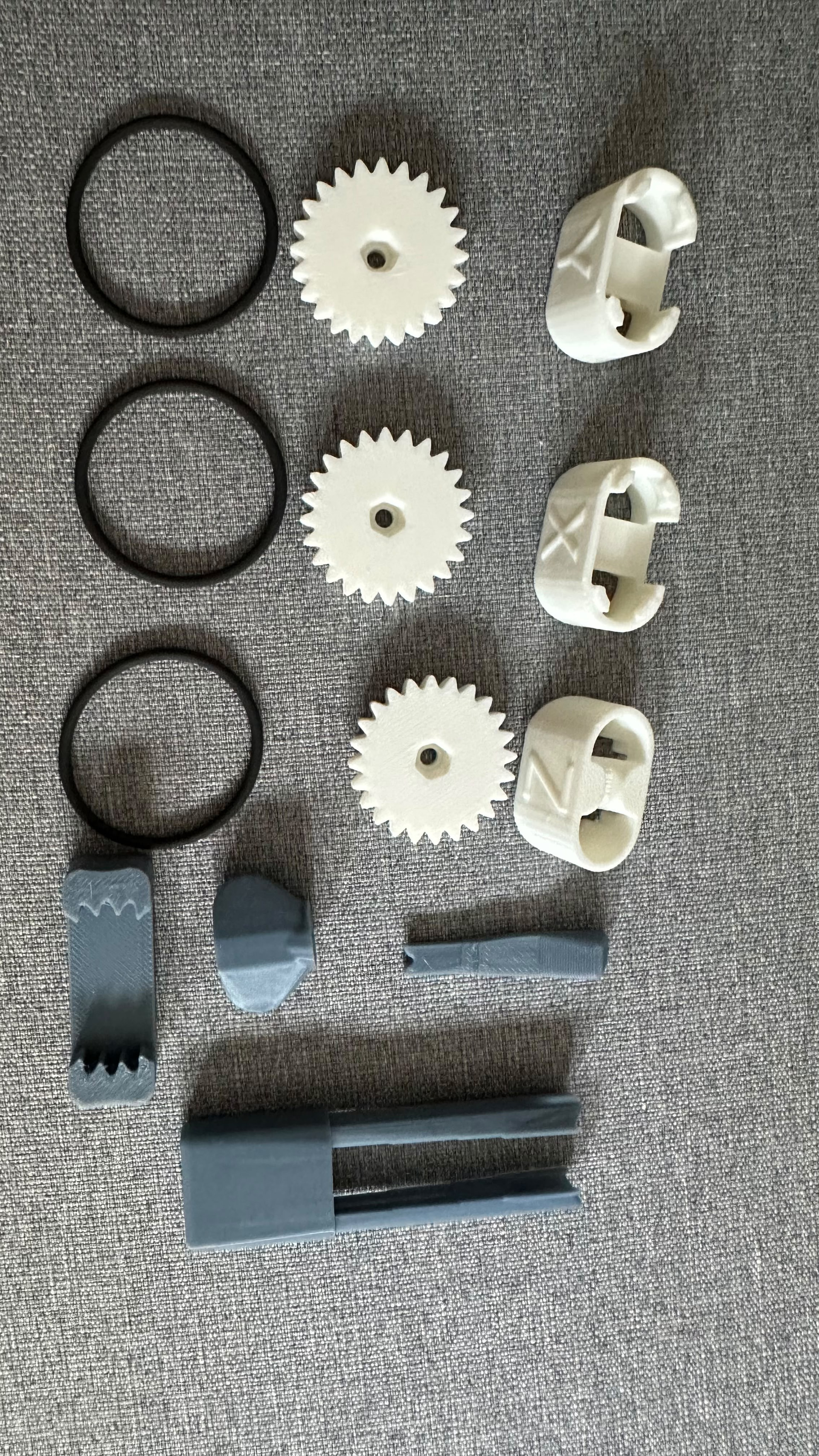
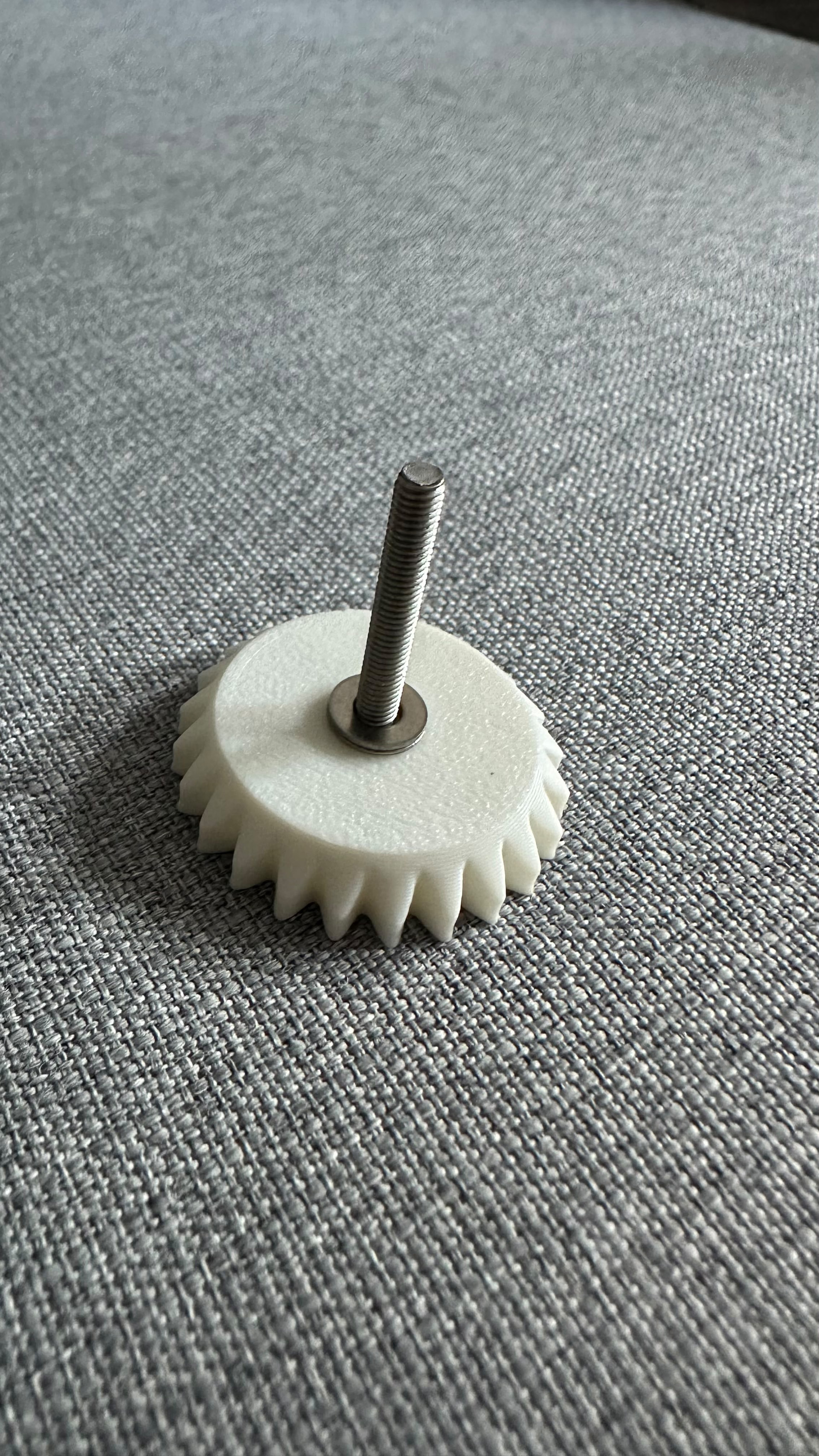
Next, prepare the 3D-printed gear. Insert the M3 × 25 mm bolt and add two washers. Make sure to use the brass nut because the original instructions specifically emphasize this. Add a small amount of oil for lubrication, place the brass nut inside, and screw the gear into place.

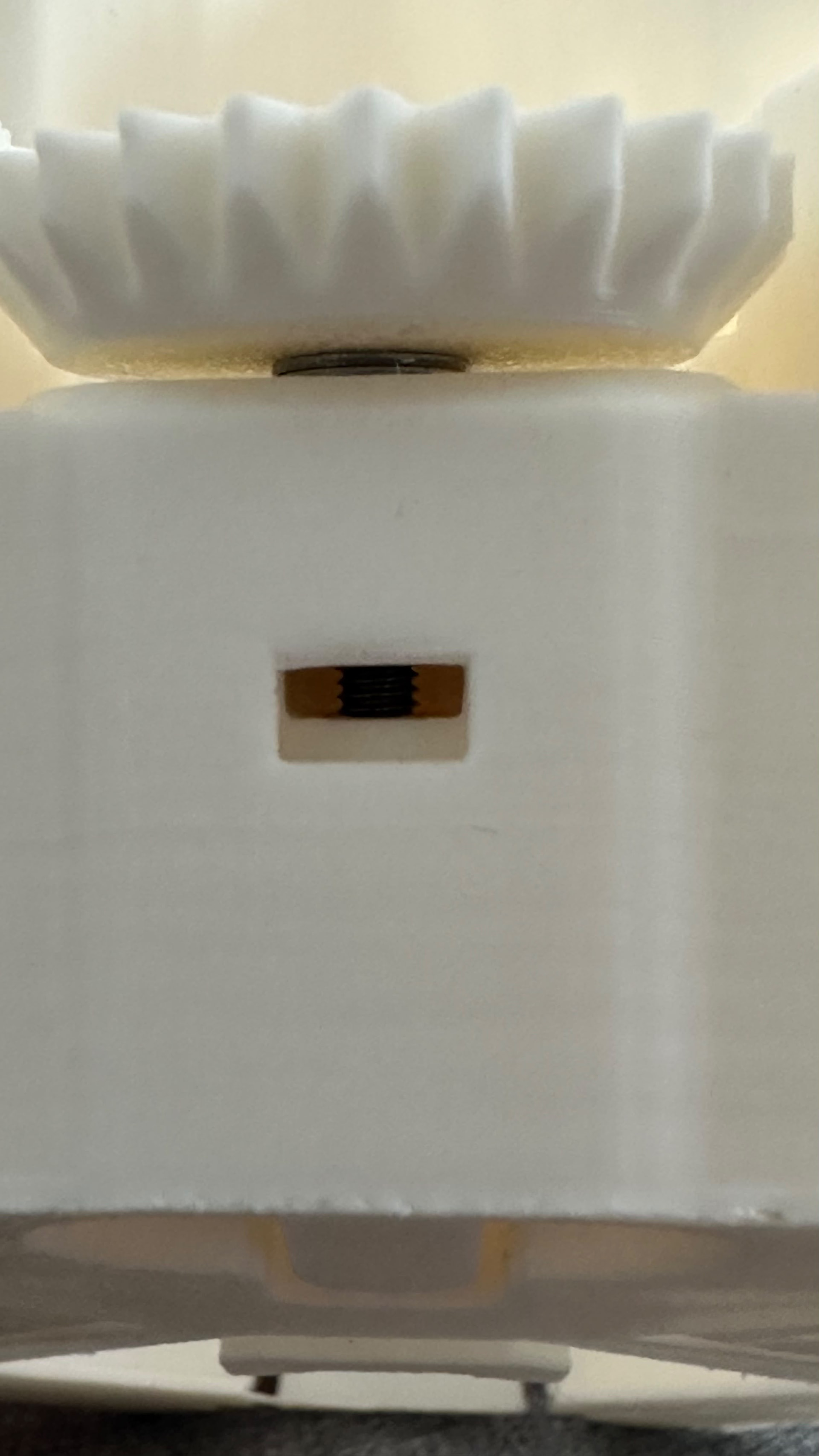
Make sure the brass nut is positioned correctly and does not block the small gap shown in the picture below.

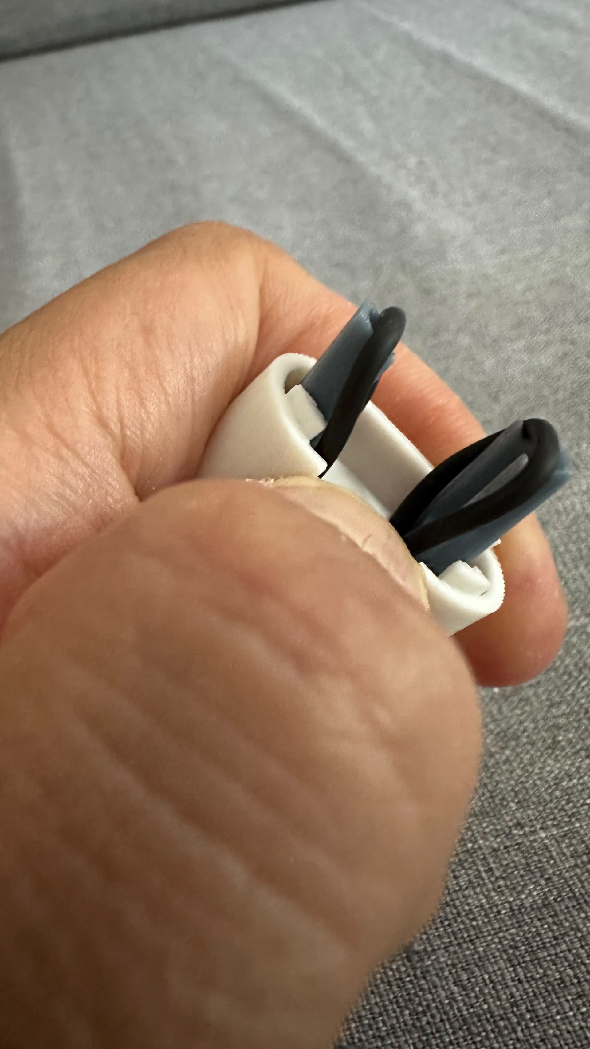
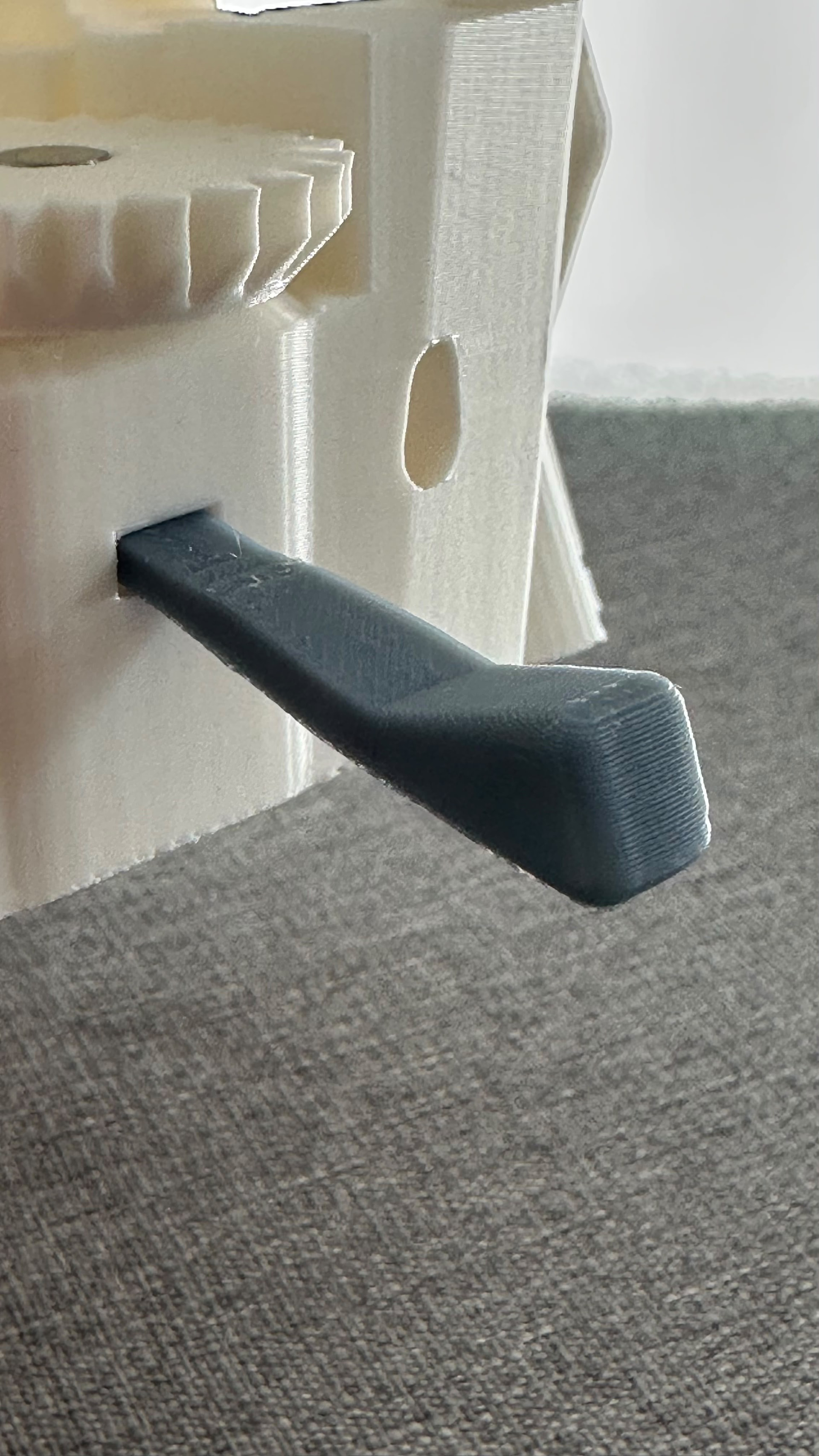
The next part is a little difficult. loop the Viton band through the foot and push the assembled band tool through it. Hook the band onto both sides of the tool, then place the foot under the microscope with the letter facing outward. Make sure the nut tool is still blocking the actuator column. Push the band tool into the microscope until the foot clicks into place, then remove the tool. If the foot does not click into position, carefully align it and push it into place by hand.

Assembling the Optics Module

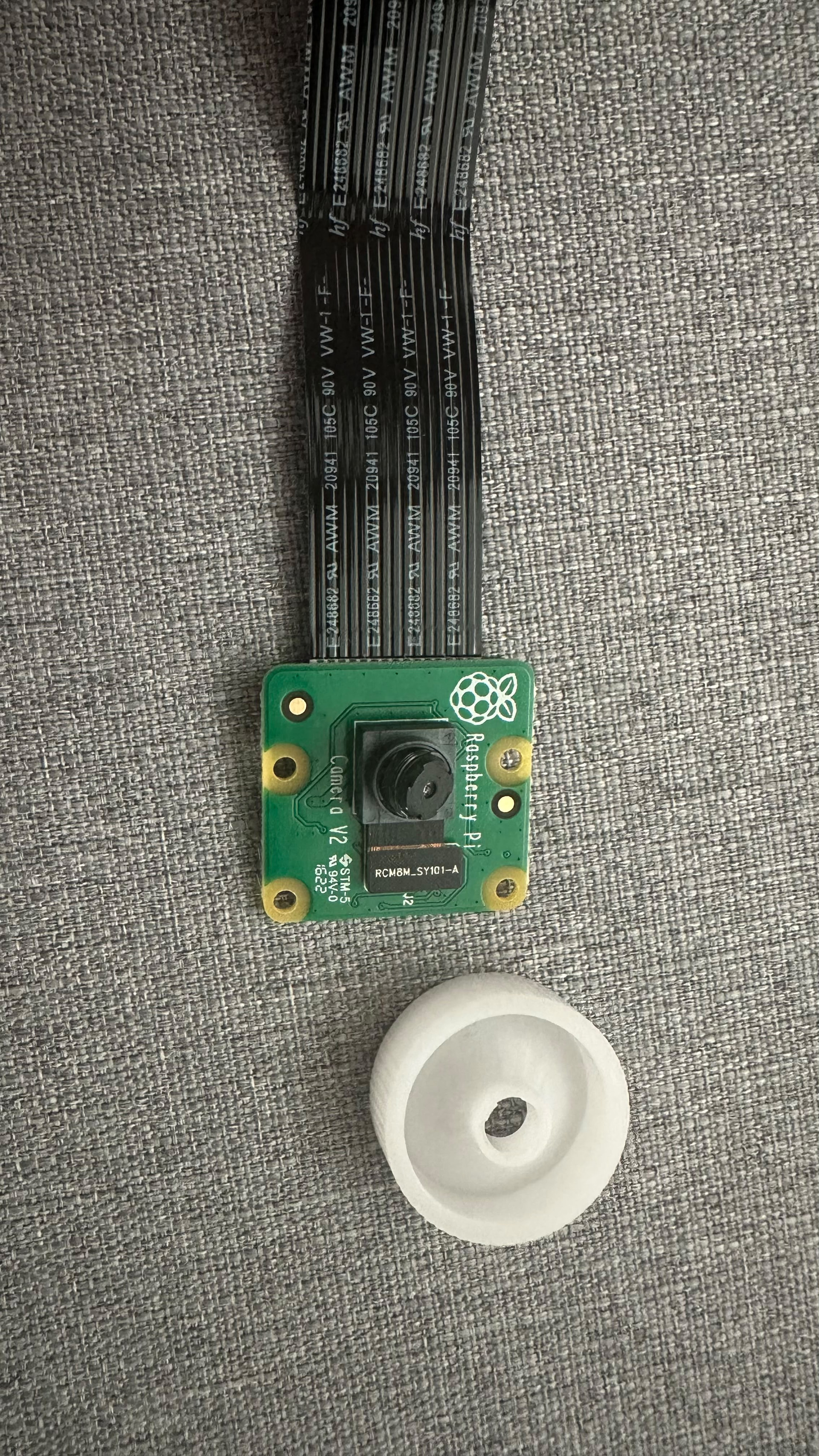
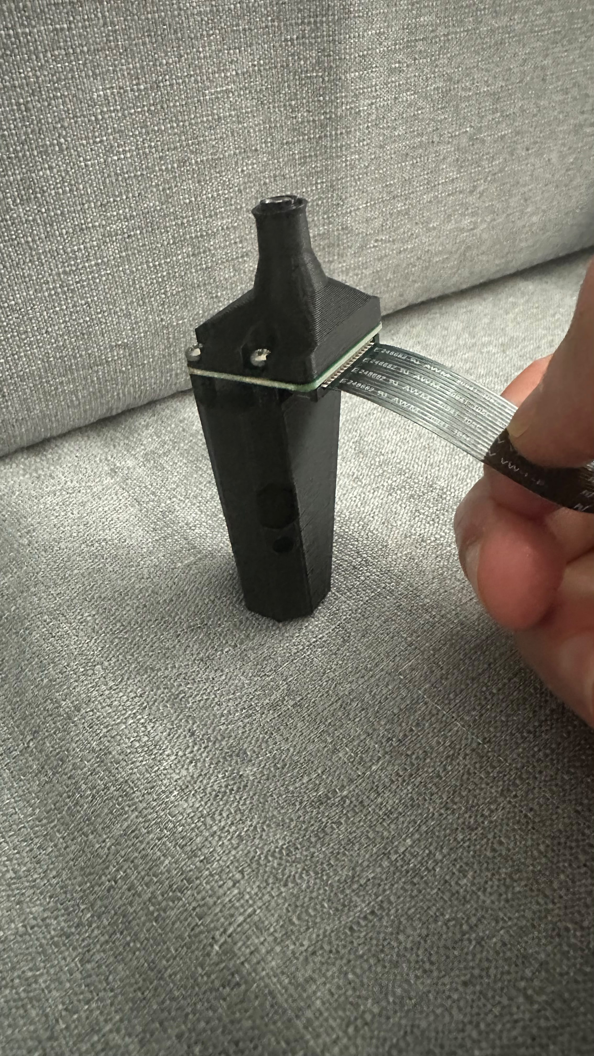
Next, I assembled the optics module using a Raspberry Pi Camera Module v2 and its original lens. I first checked that the black lens spacer was clean and that no plastic strings were blocking the center hole.

Before handling the camera, I touched a grounded metal object to remove static electricity and held the camera board only by its edges. I removed the protective film and used the small lens tool that came with the camera to slowly unscrew and remove the lens.

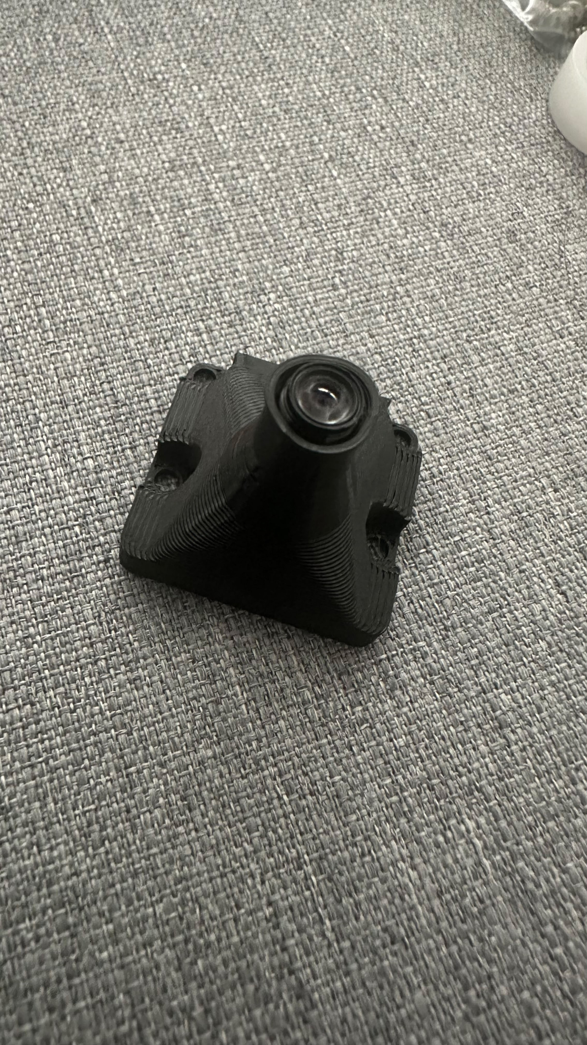
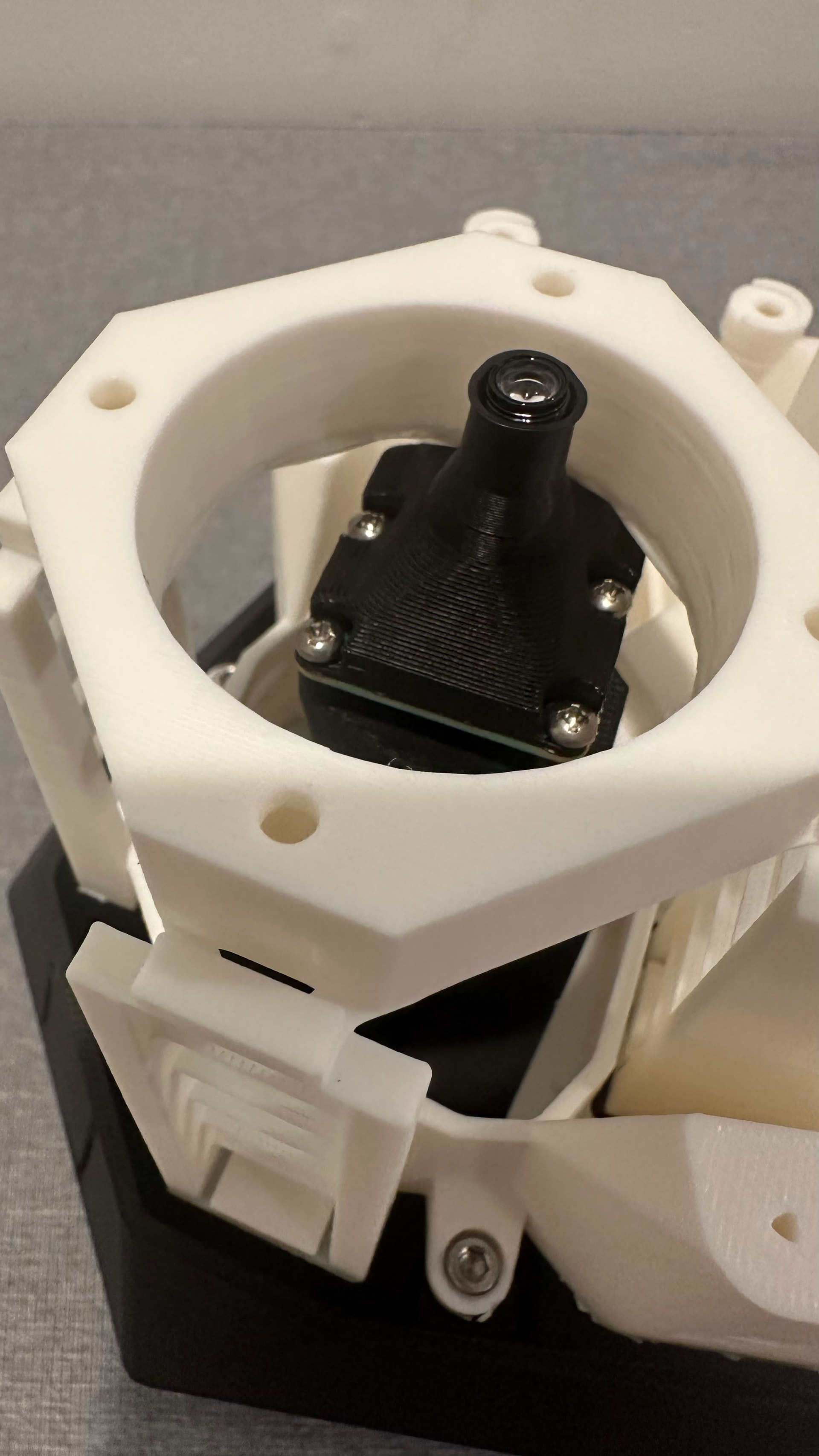
I reversed the lens so that the side that originally faced the camera sensor was facing down. I then pushed the lens spacer onto it until it clicked into place. After that, I placed the camera and spacer on the camera platform and secured everything with four No. 2 × 6.5 mm self-tapping screws. I tightened them carefully because the printed parts could be damaged if the screws were overtightened.

I pushed an M3 nut into the slot on top of the platform and inserted an M3 × 10 mm screw. I only turned it a few times and left about 5 mm of the screw exposed.

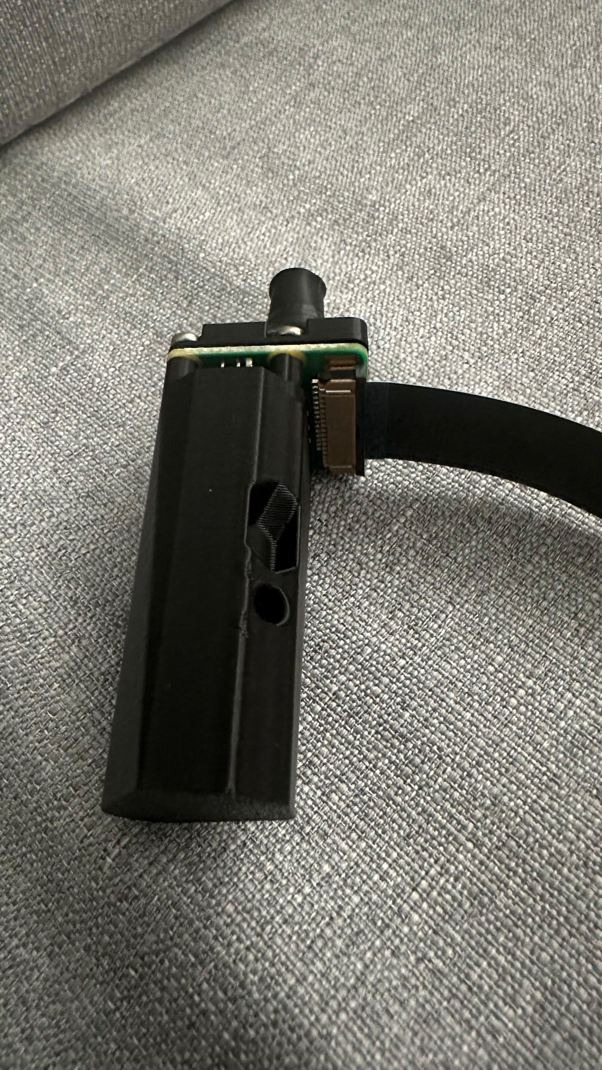
Next, I connected the 200 mm Type B ribbon cable. It is important to check that the metal contacts are on opposite sides at the two ends. The instructions warn that using the wrong cable can quickly damage the camera.

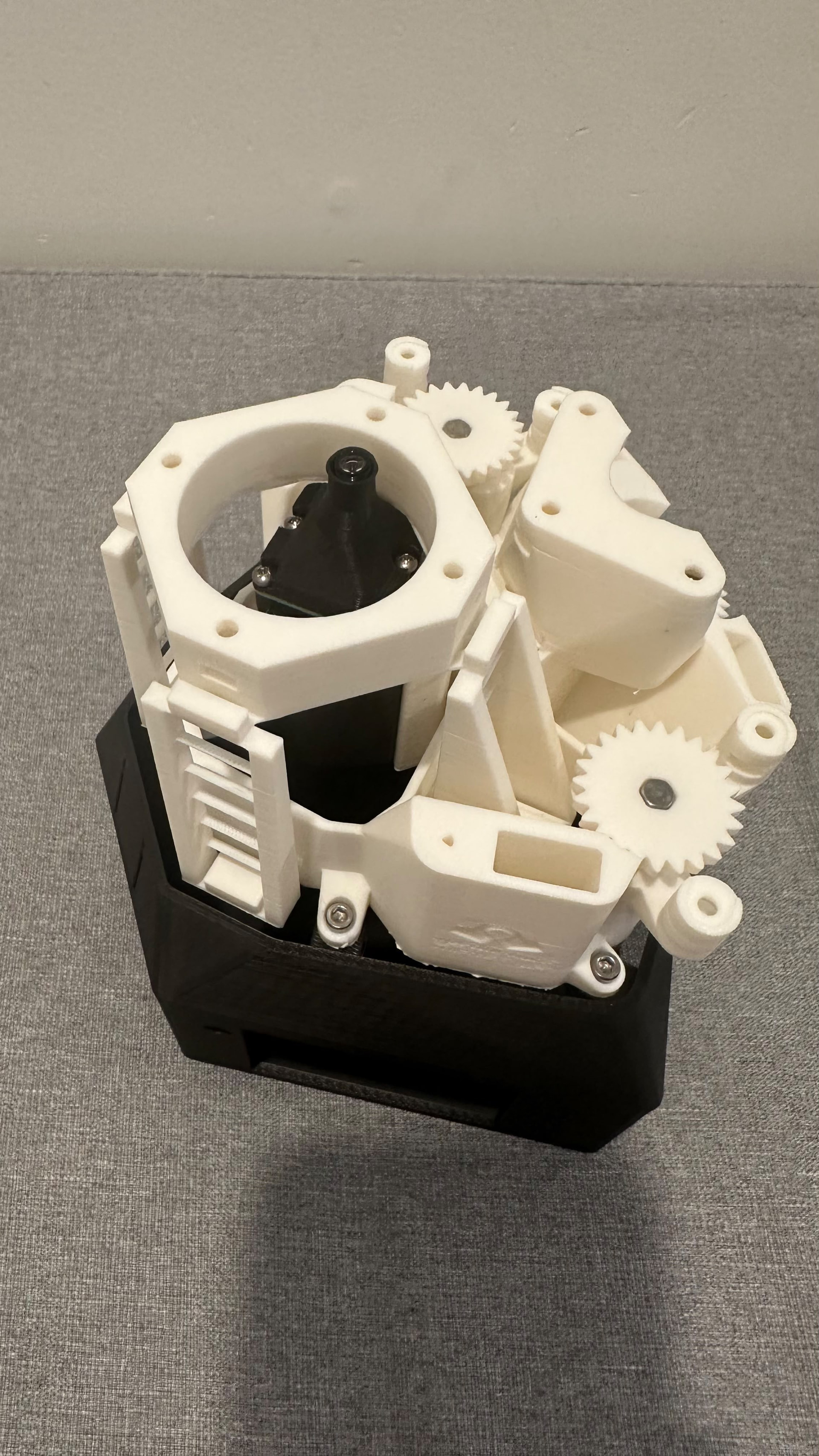
I passed the completed optics module through the bottom of the microscope and placed the exposed screw into the keyhole on the Z-actuator. I pushed the module upward and used a 2.5 mm ball-end Allen key through the front hole to tighten it.

Finally, I placed the microscope on the stand, aligned the mounting points, and secured it with four M3 × 10 mm screws.