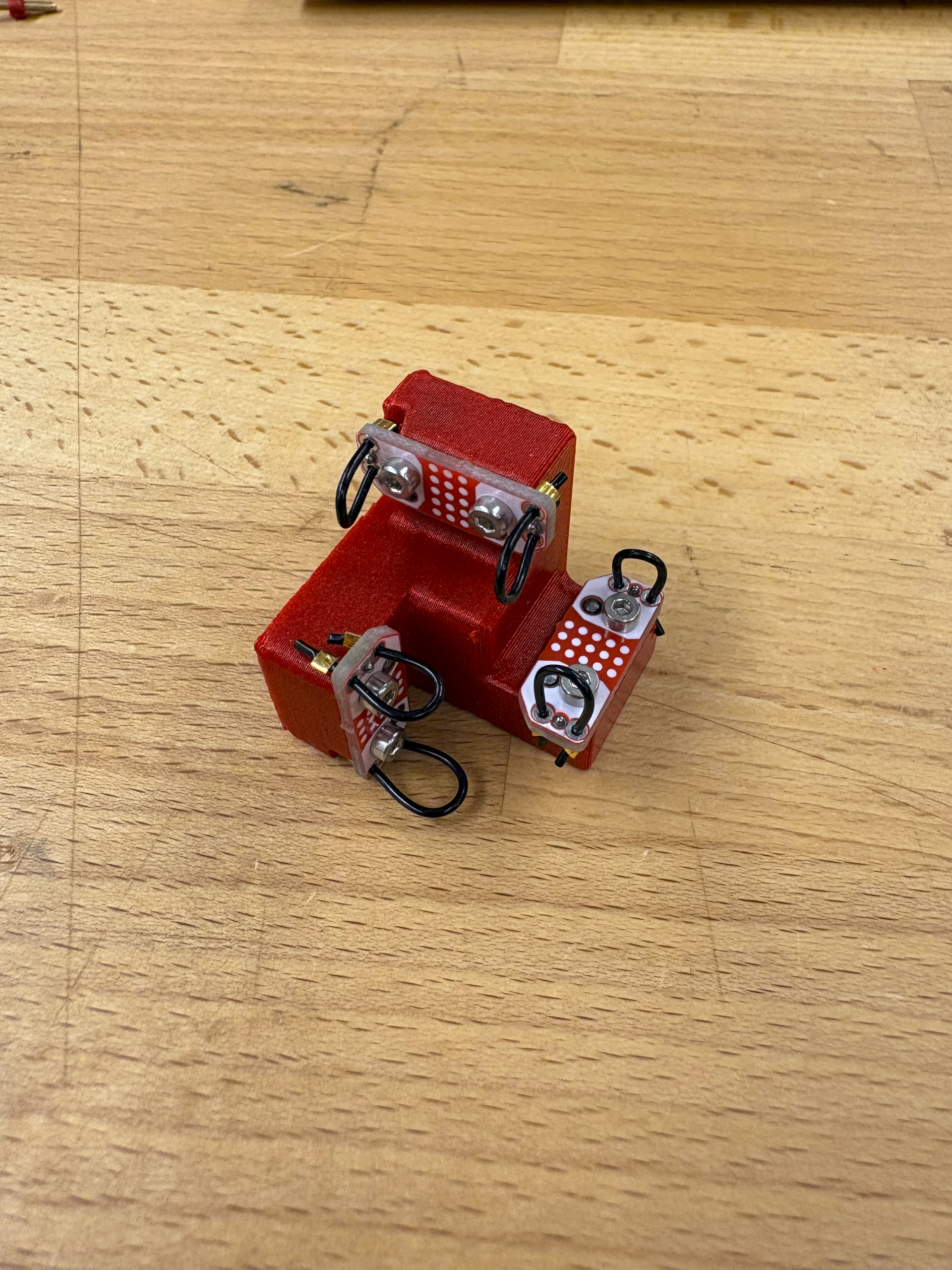
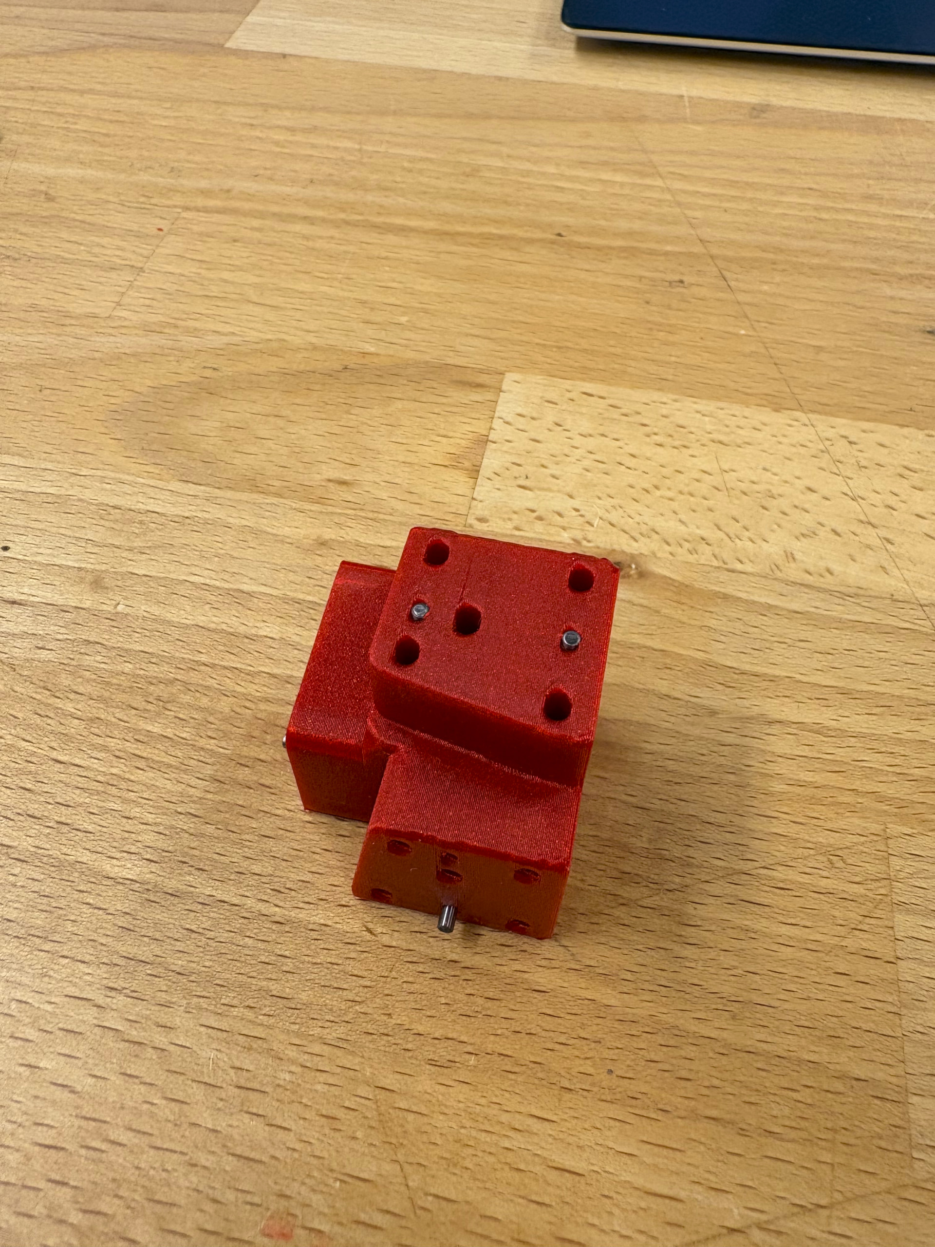
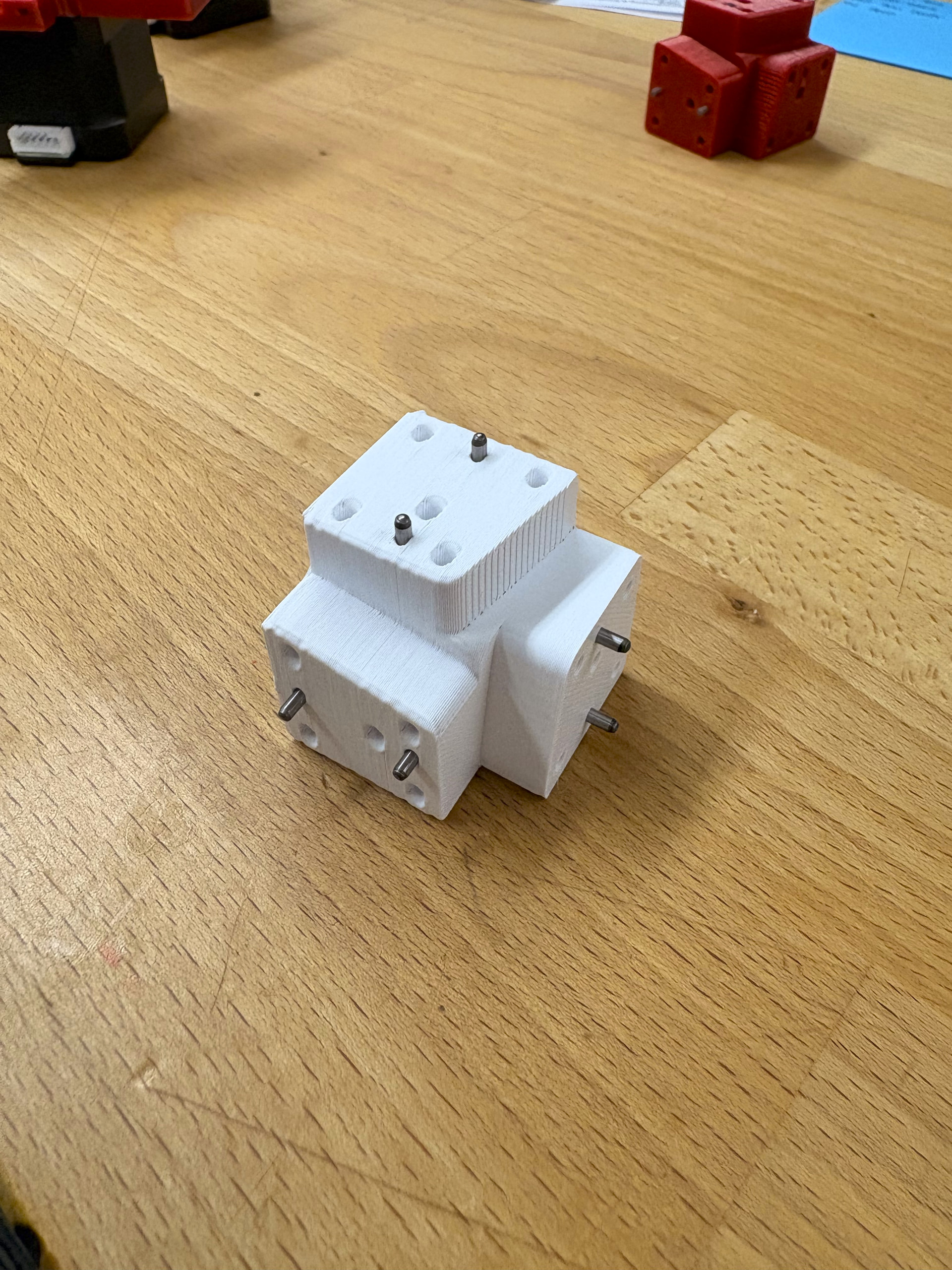
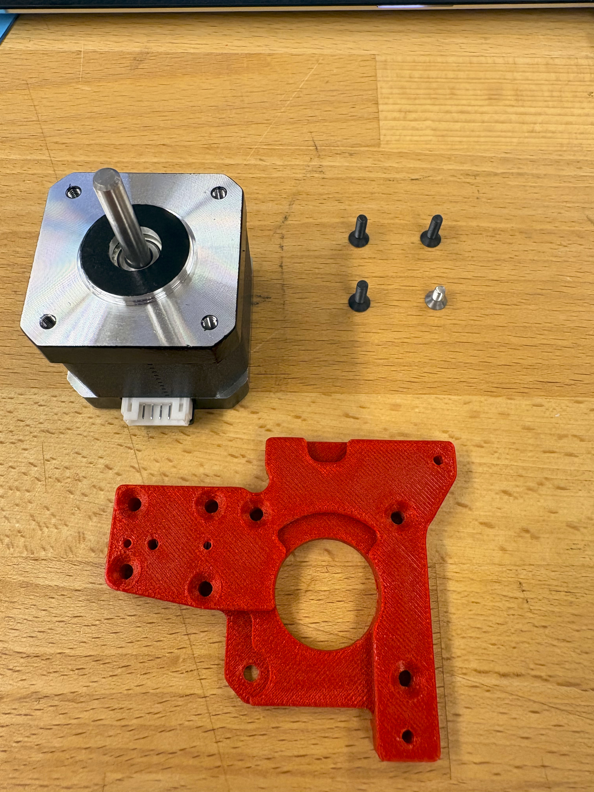
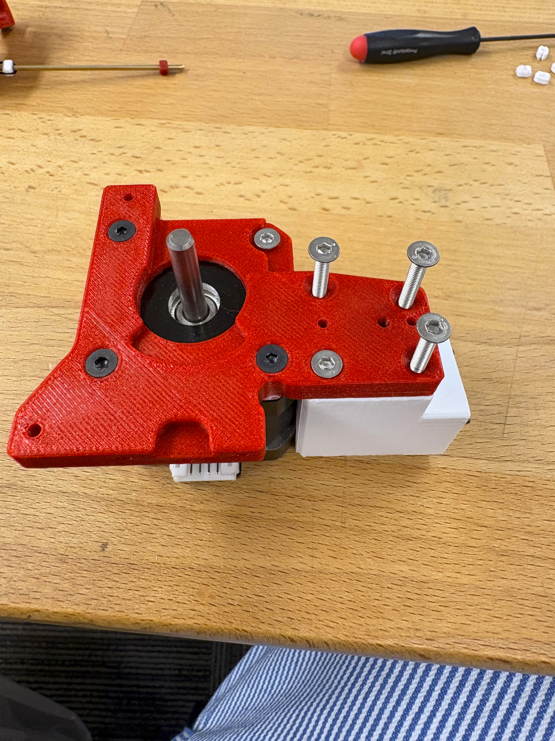
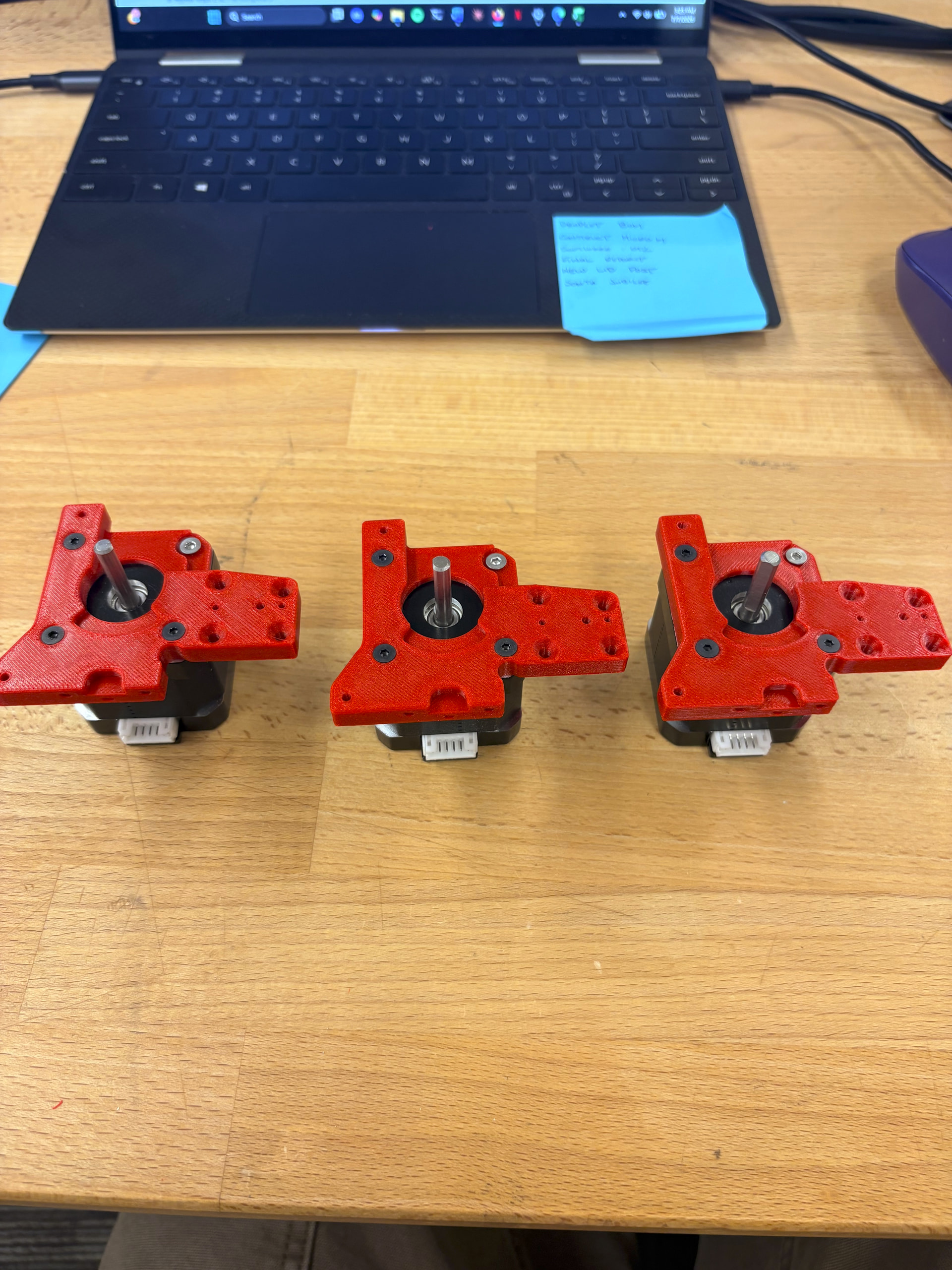
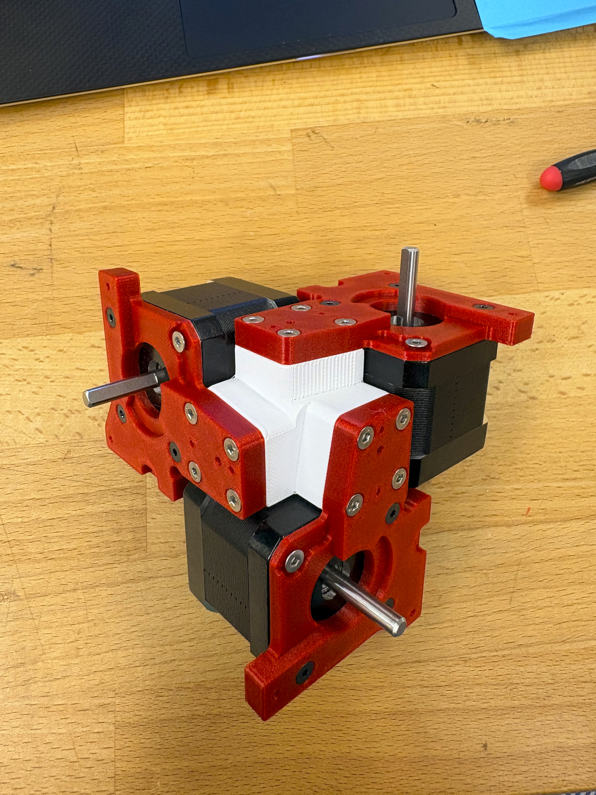
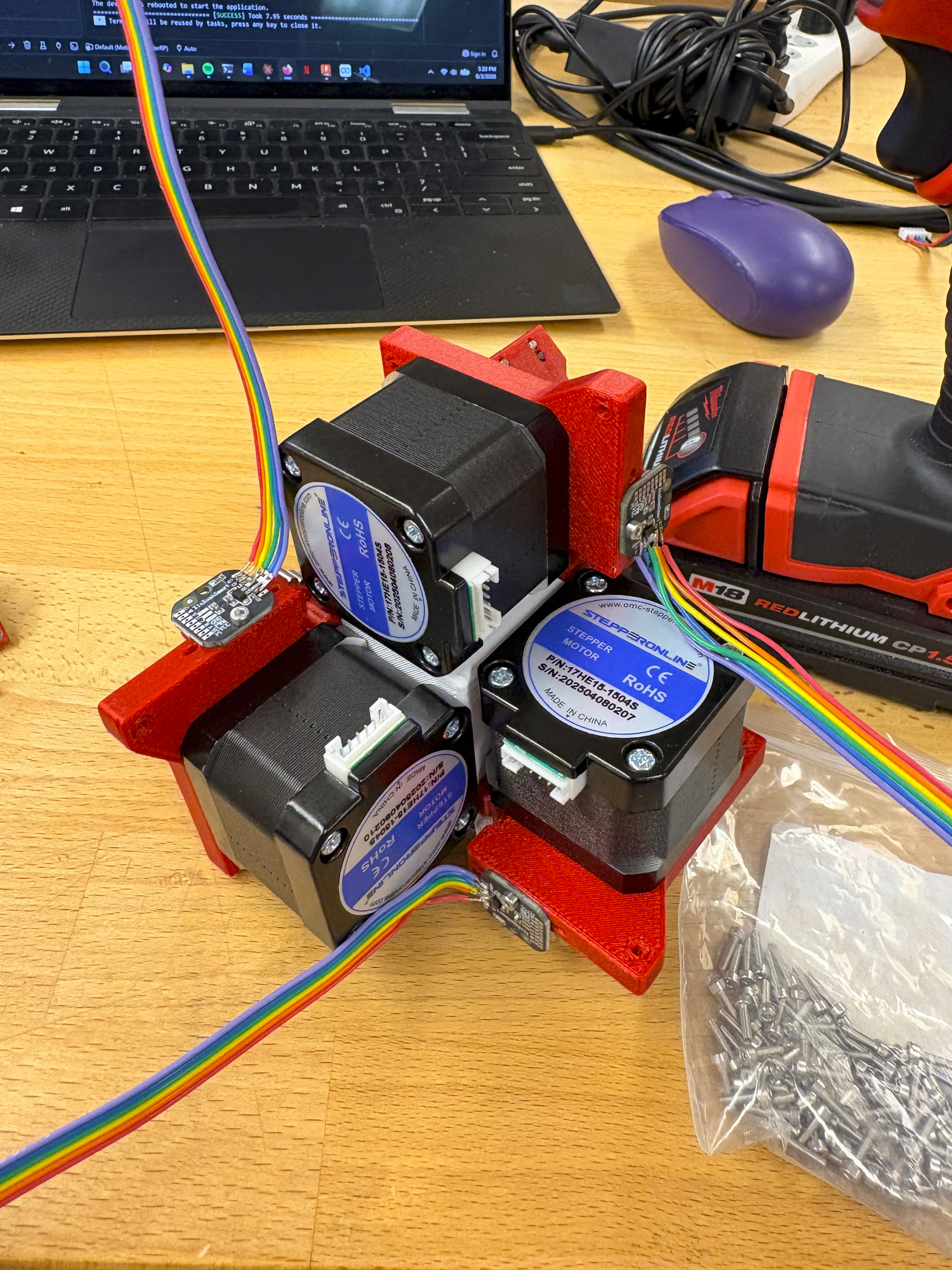
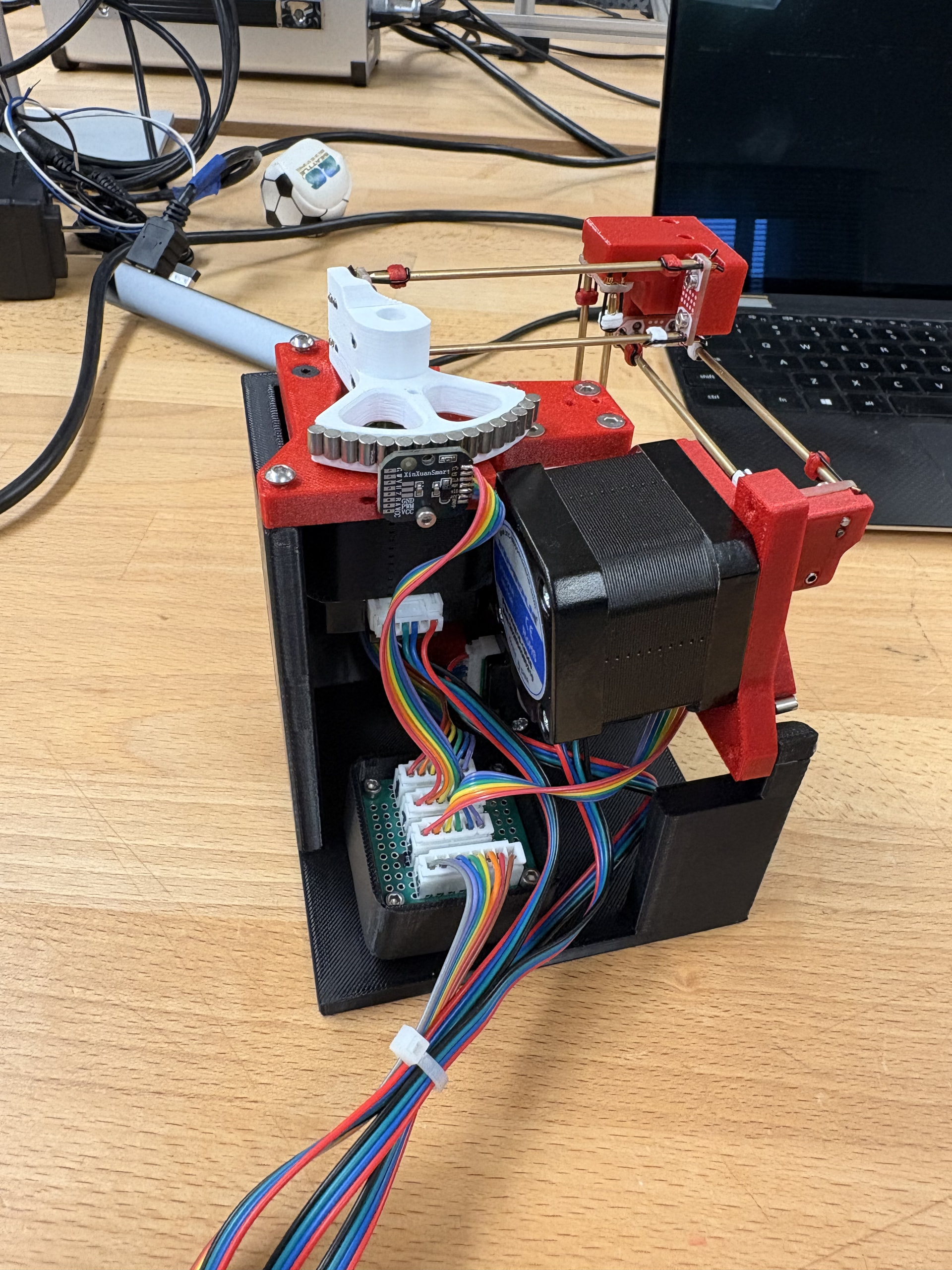
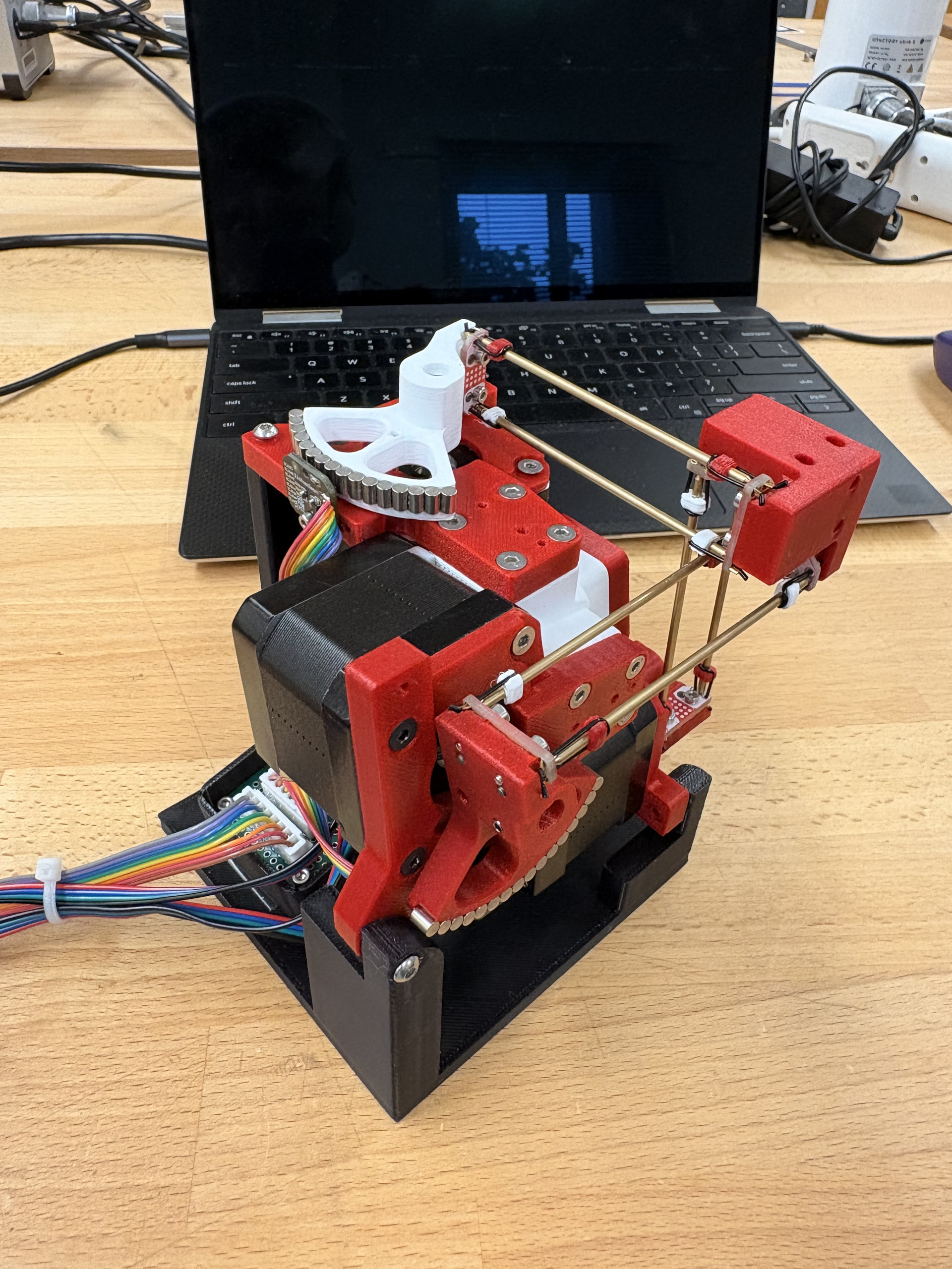
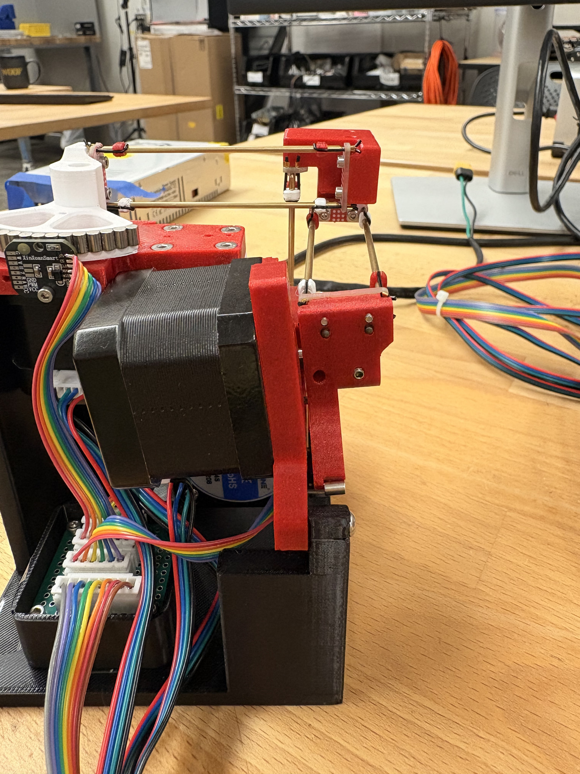
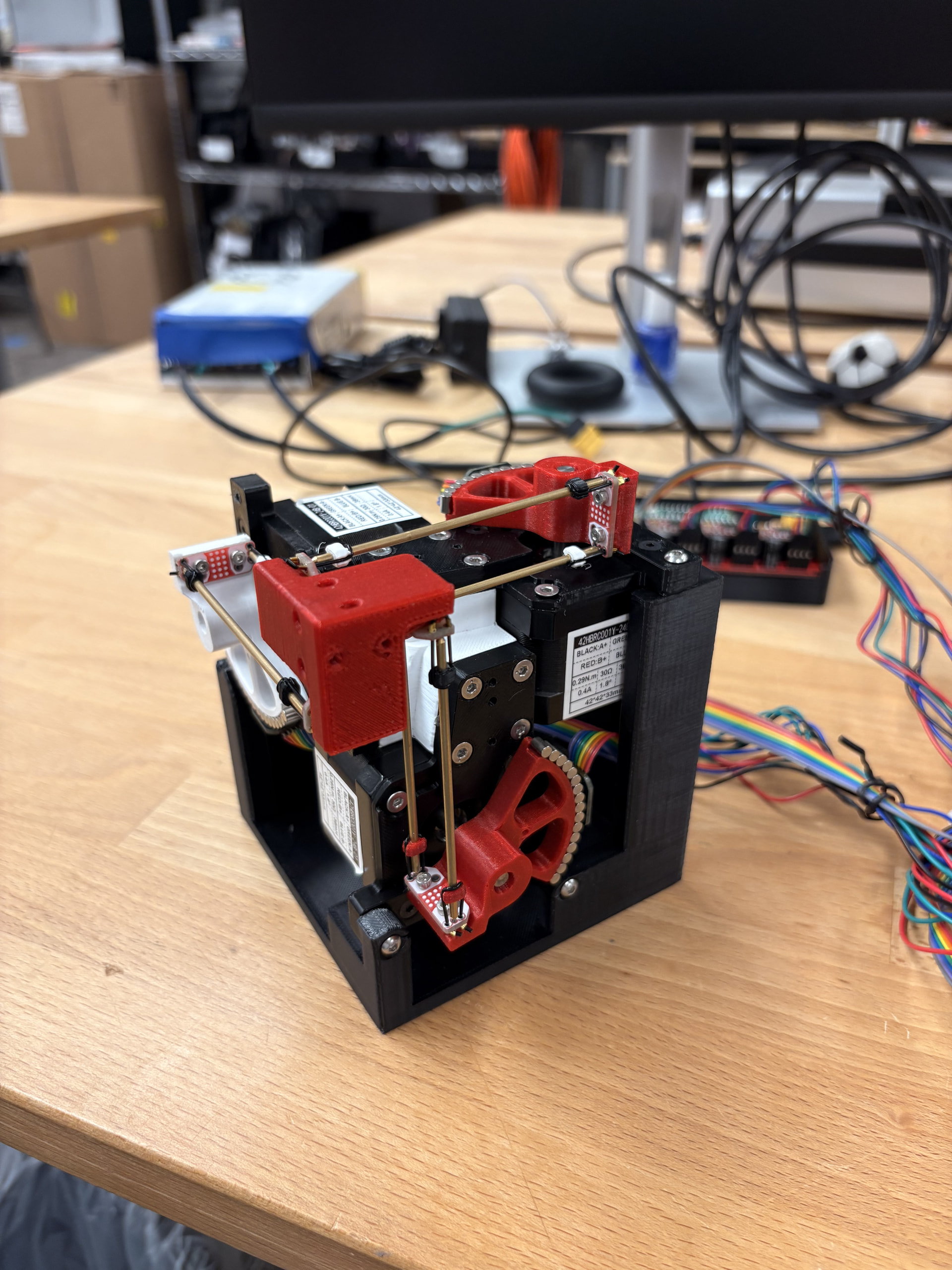
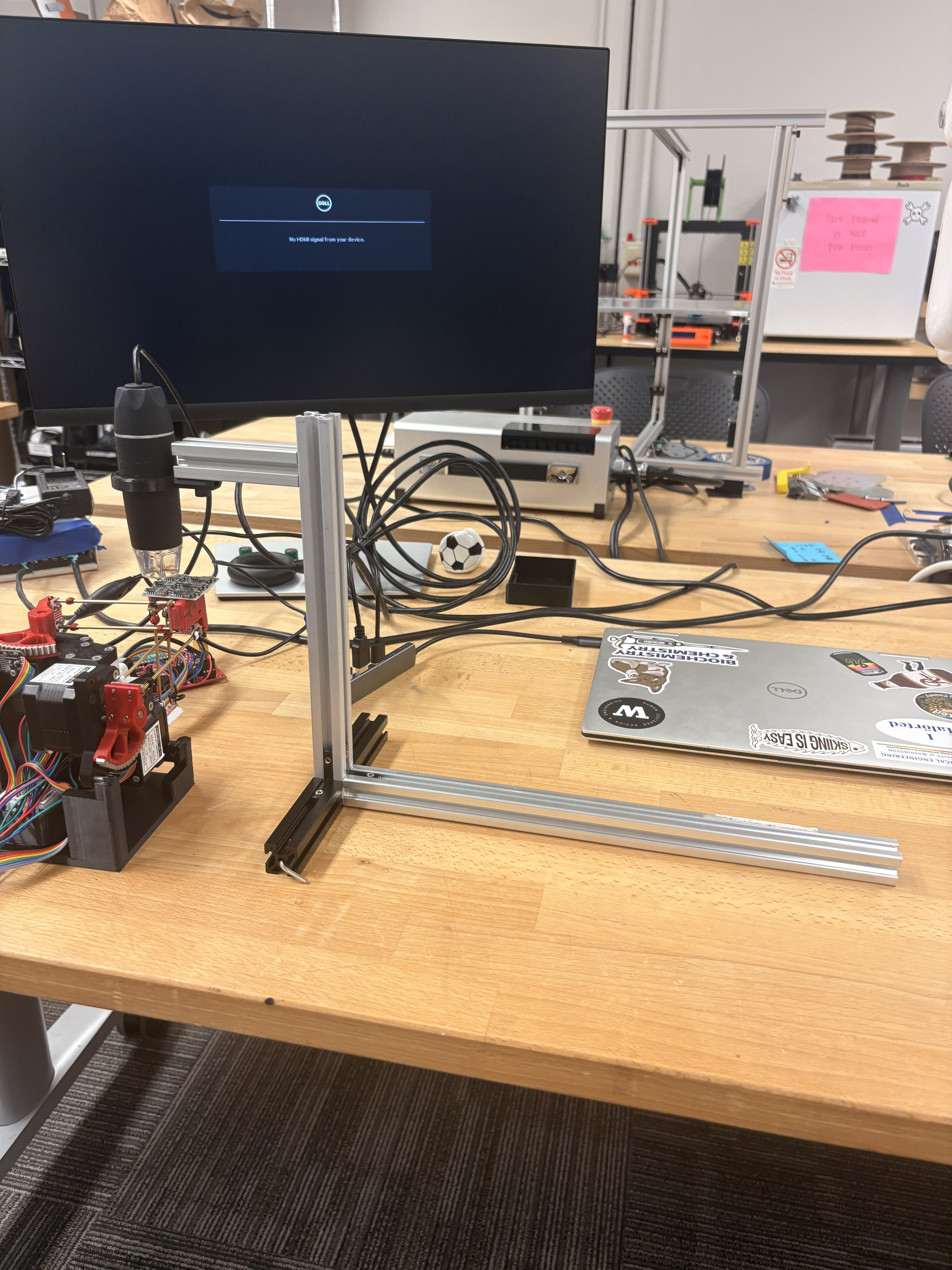
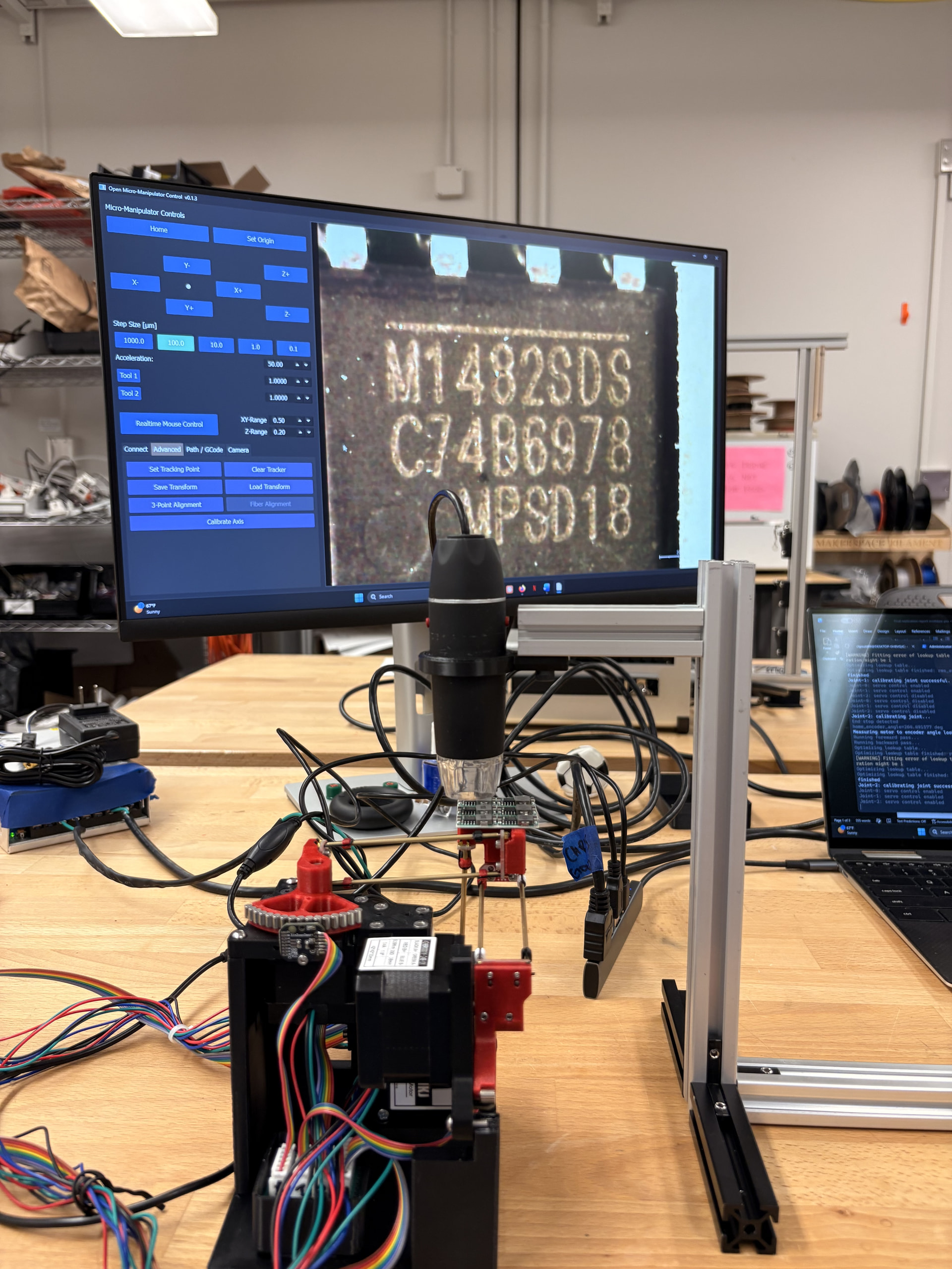
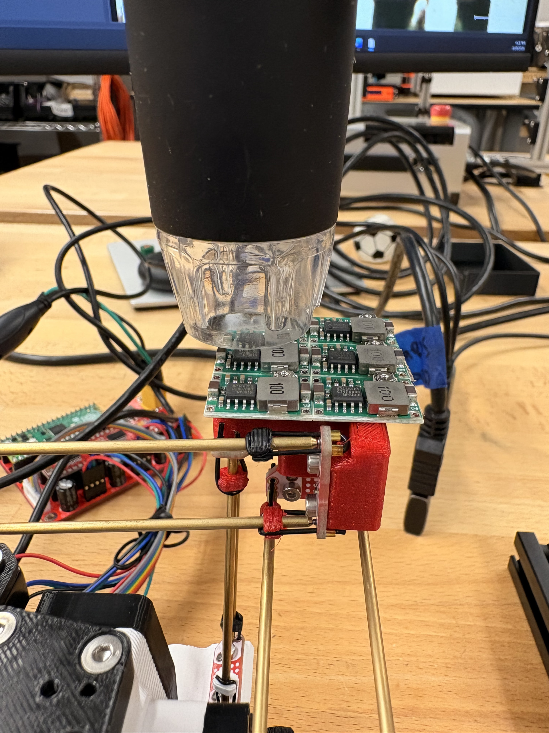
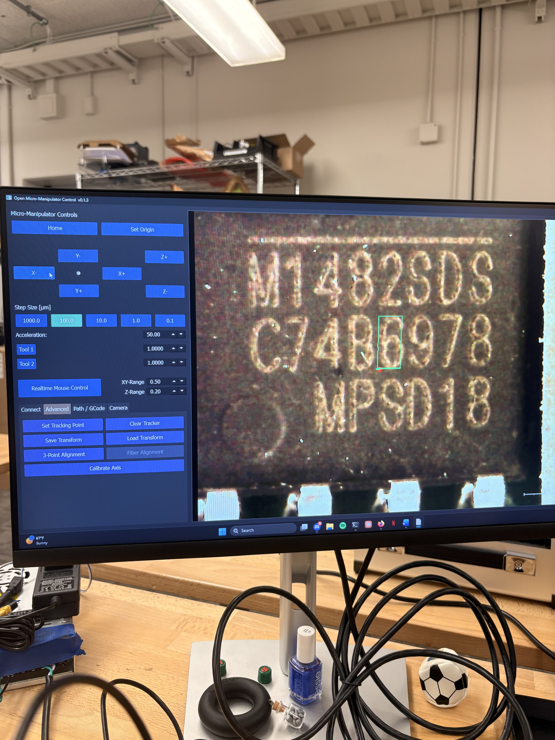
I am in the process of replicating the XYZ micro-manipulator by Diffraction Limited. This is a motorized motion platform that can achieve repeatable sub-micron precision. As of February this year, Diffraction Limited updated the ball joint design and manufacturing process which I will be using in this replication.
This replication will be interesting because documentation is spread out between Github, Youtube, an active discord server, and few guilds on StepWiseDocs.
The last item of the BOM should be arriving this week. I will be documenting the process in the replies below.
2 Likes
BOM
When I started this replication, I used the Bill of Materials listed on the MircroManipulatorStepper repo on Github and YouTube videos as a reference for ordering my components. It wasn’t until I started exploring the StepWiseDocs BOM and build guilds that I found that the repo’s BOM is incomplete and has some deprecated parts. If you are going to replicate this project, use the BOM from StepWiseDocs.
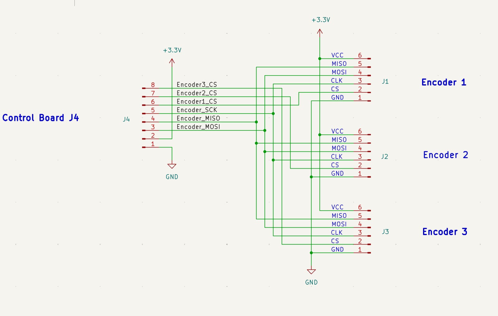
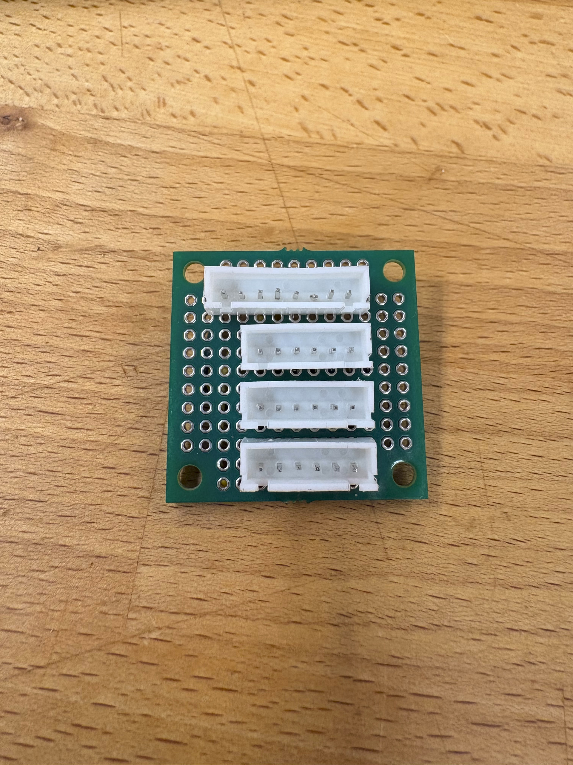
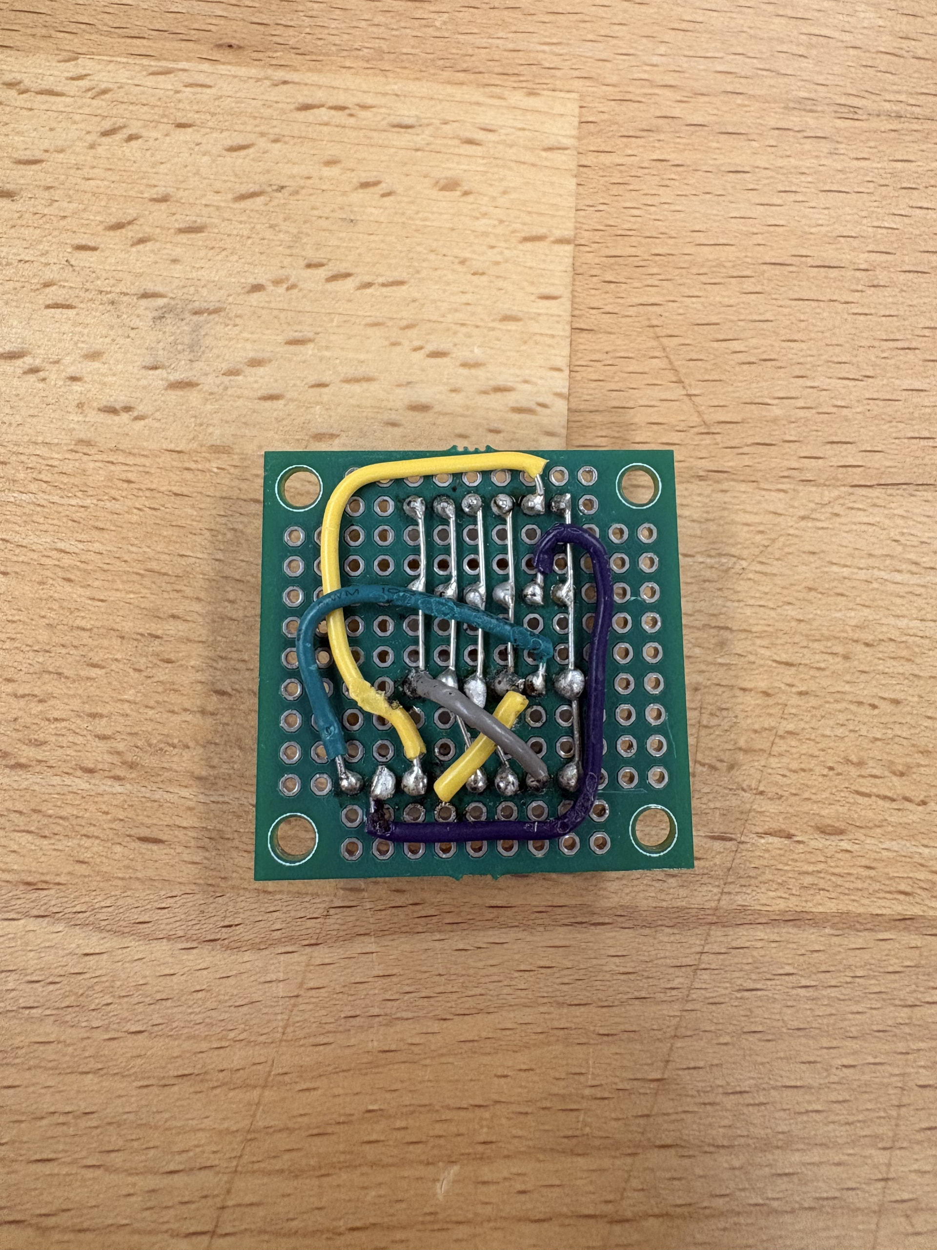
The Github repo’s BOM has not been updated for the new precision ball joint arms so note that the 2mm brass pipe listed should be a 2mm brass rod. Other materials like calipers, a mallet, sandpaper, glue, JP weld, XT60 connectors, JST ph 6 headers, crimp beads, and the encoderboard PCB are not listed on the Github BOM.
I have started construction of the ball joint arms and I would like to point out that it would be valuable to have a few spare materials. Specifically extra brass rods, 1mm ball bearings, ball joint plate PCBs, and Ball alignment disc PCBs. I had one or 2 rods and ball joint plates that didn’t turn out perfectly on my first attempt but luckily I had extra materials to work with.
I had little trouble ordering all of my materials with the exception of the magnetic encoders. I originally picked a vendor through amazon that could not complete my order so I am now waiting for the encoders through Aliexpress. The StepWiseDocs BOM has multiple links for each component.
2 Likes
Precision Ball Joint Rods
As mentioned previously, there has been a update to the micro-manipulator that includes improved ball joints. This new design involves more manufacturing tools and steps but result in lower friction joints and higher dimensional accuracy.
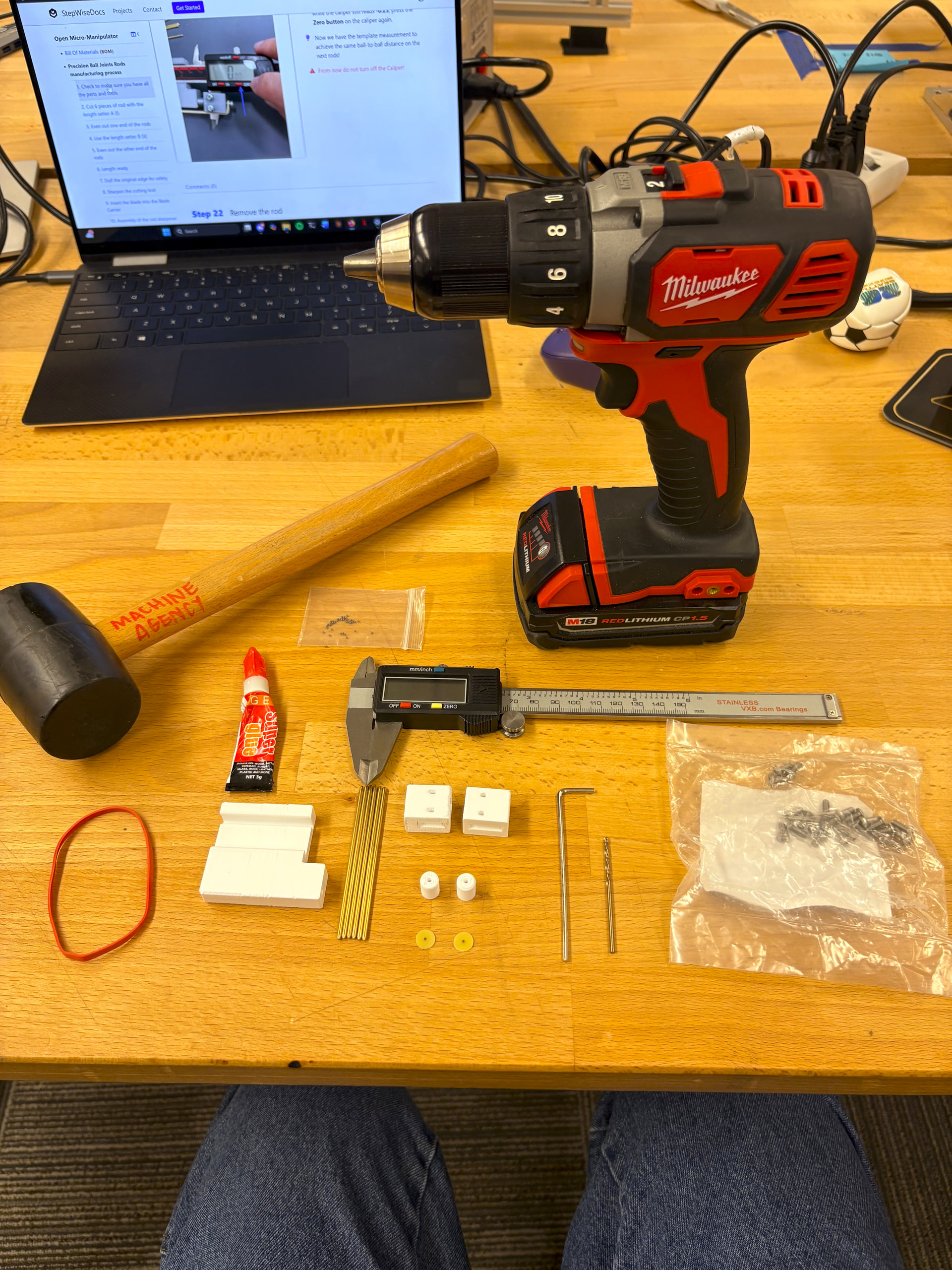
I followed the YouTube video for this process and here are my notes:
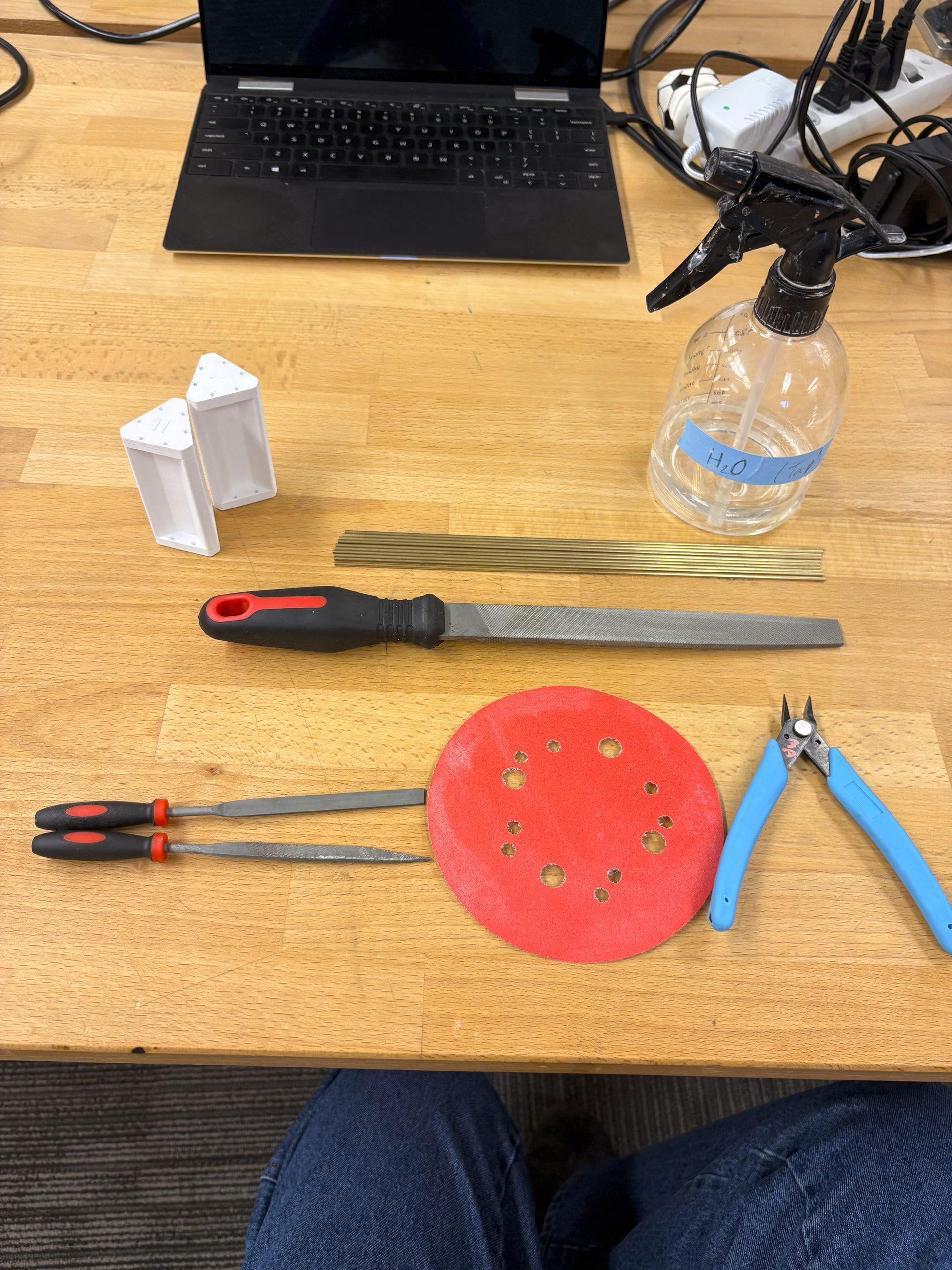
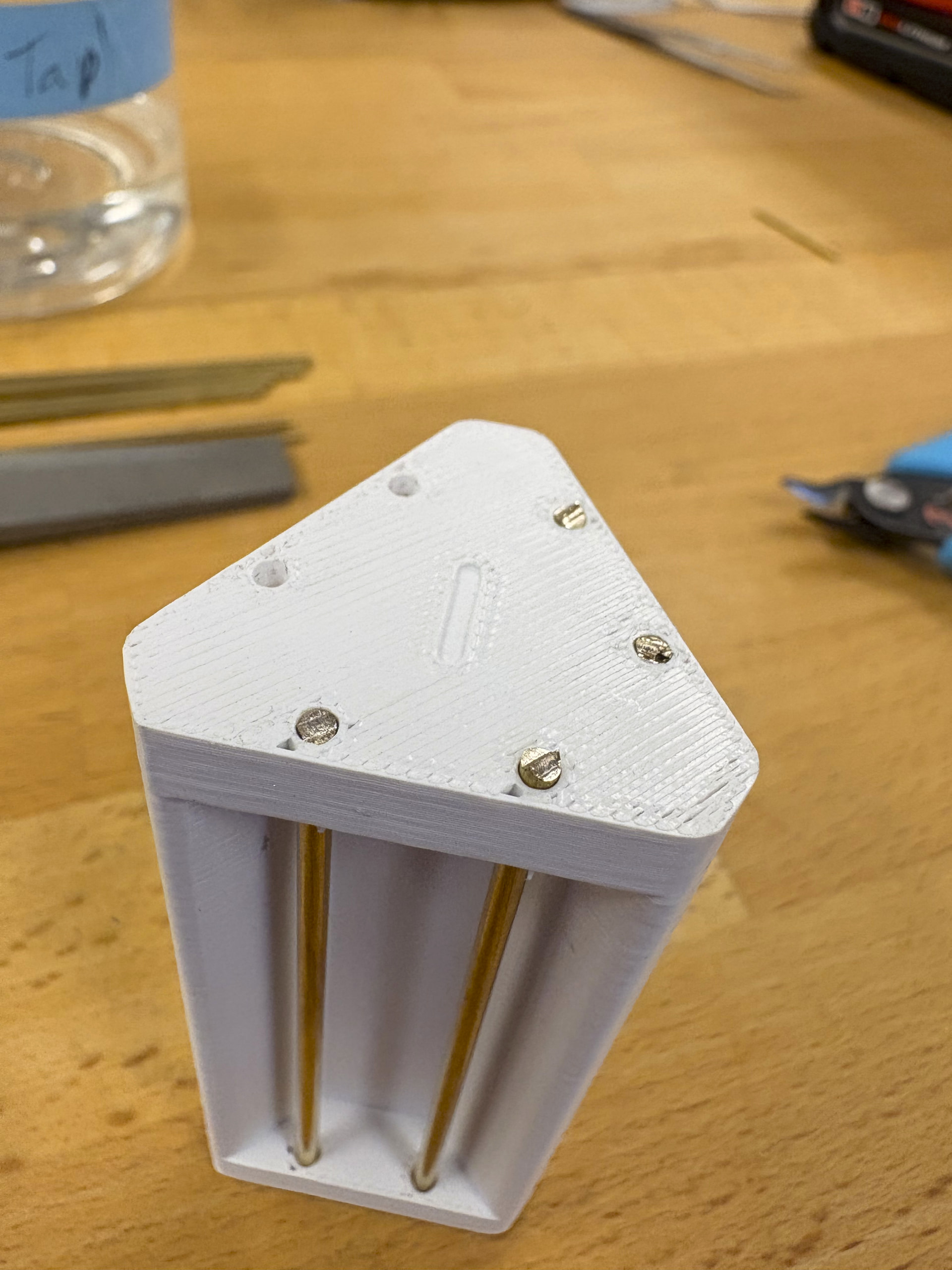
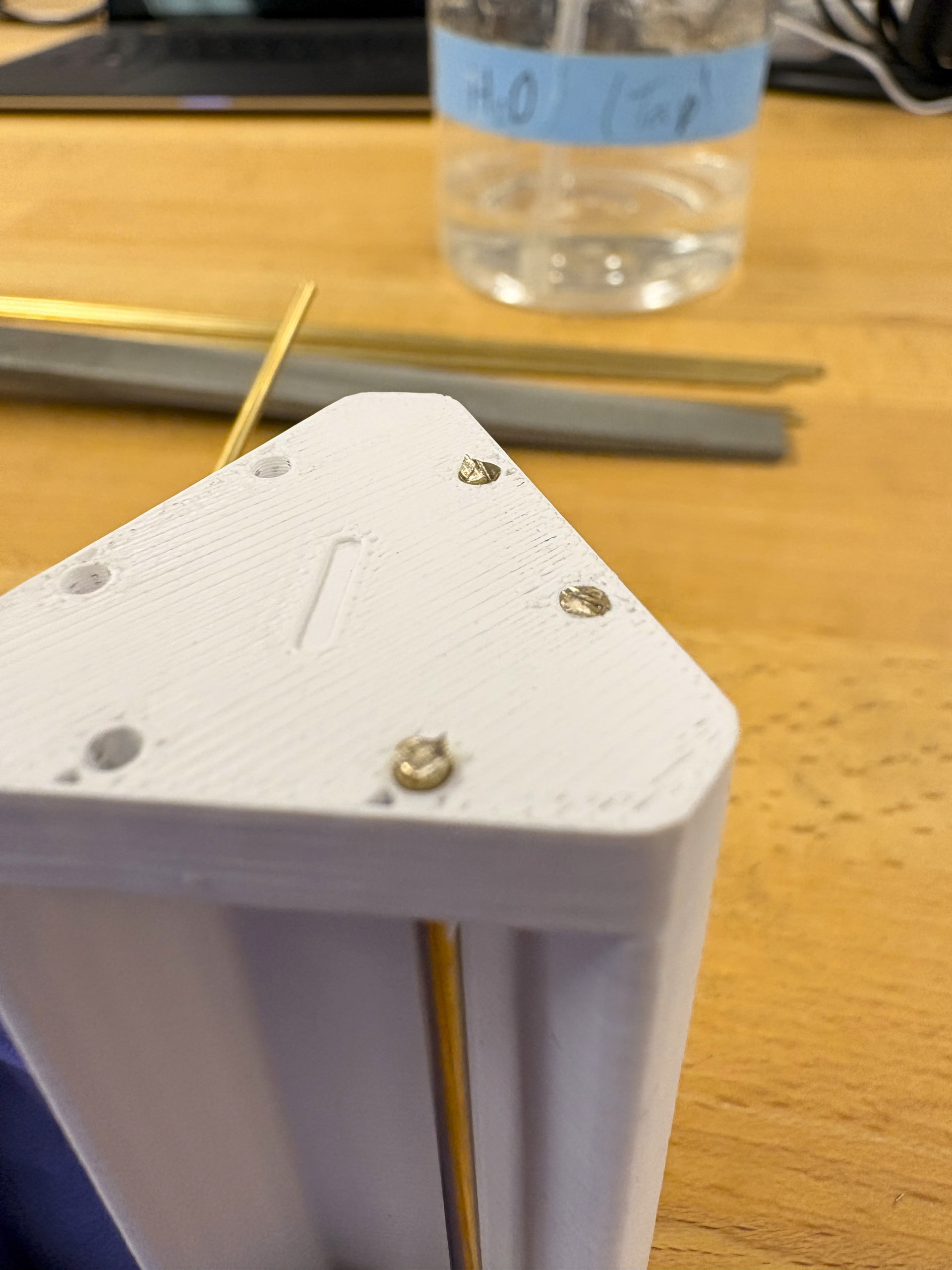
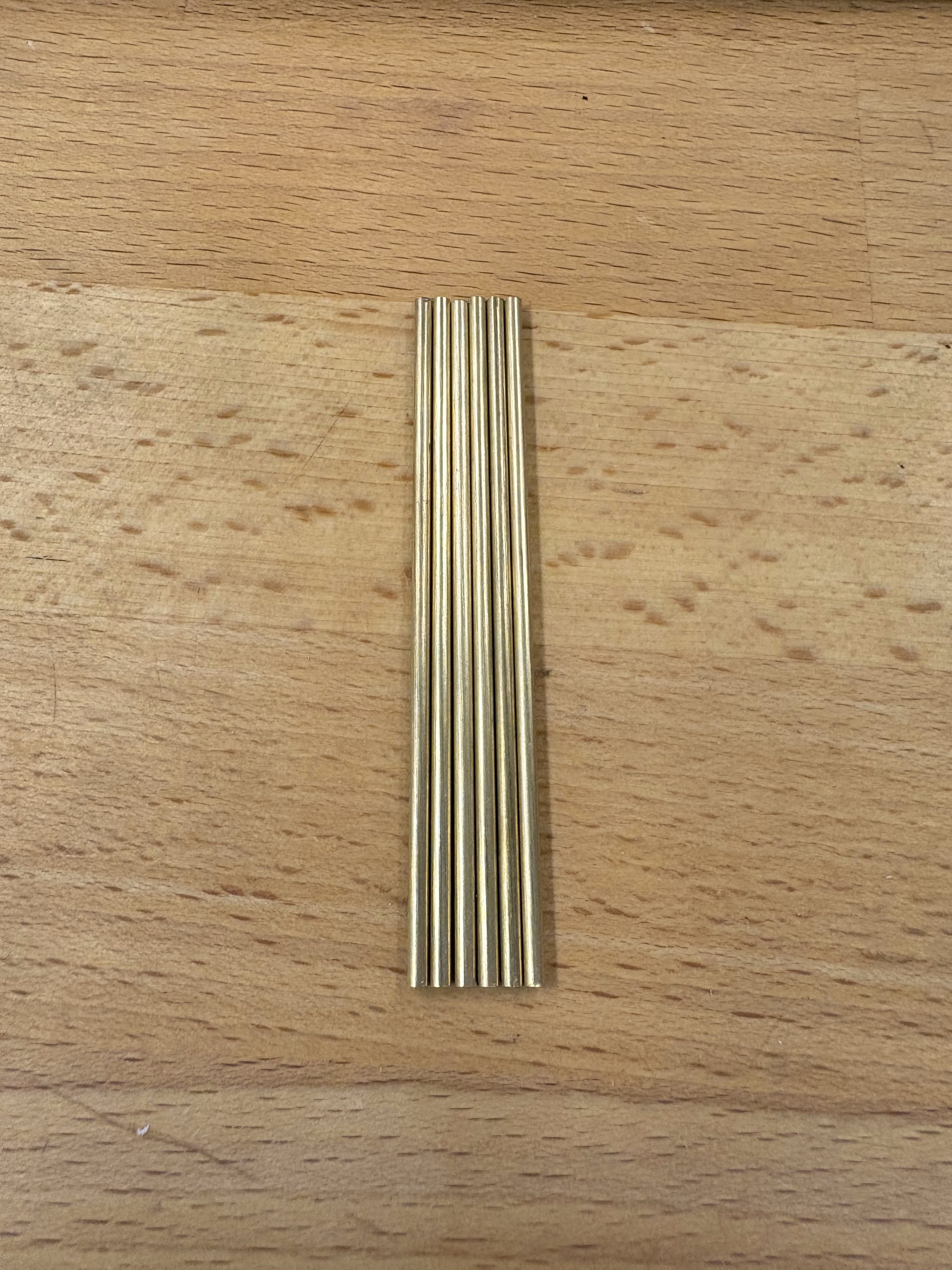
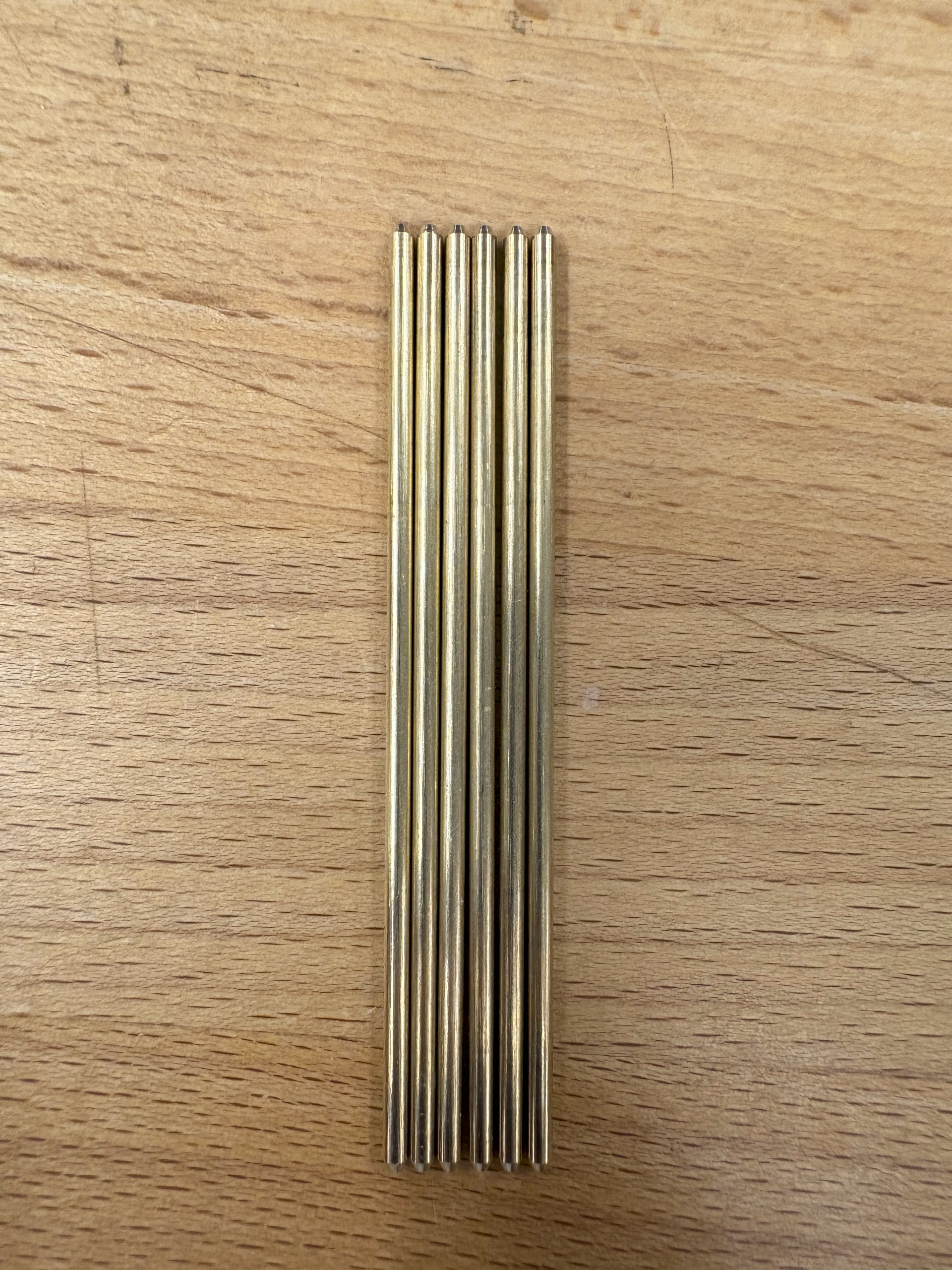
I purchased 2mm solid brass rods which are not listed in the Github BOM, but are in the StepWiseDocs BOM. They were easy to cut using metal snips/ pincers but they sometimes left uneven edges. When I cut the rods flush with the sanding jog, they would sometimes shear below the sanding line. I made sure to cut them a few millimeters longer to avoid this.
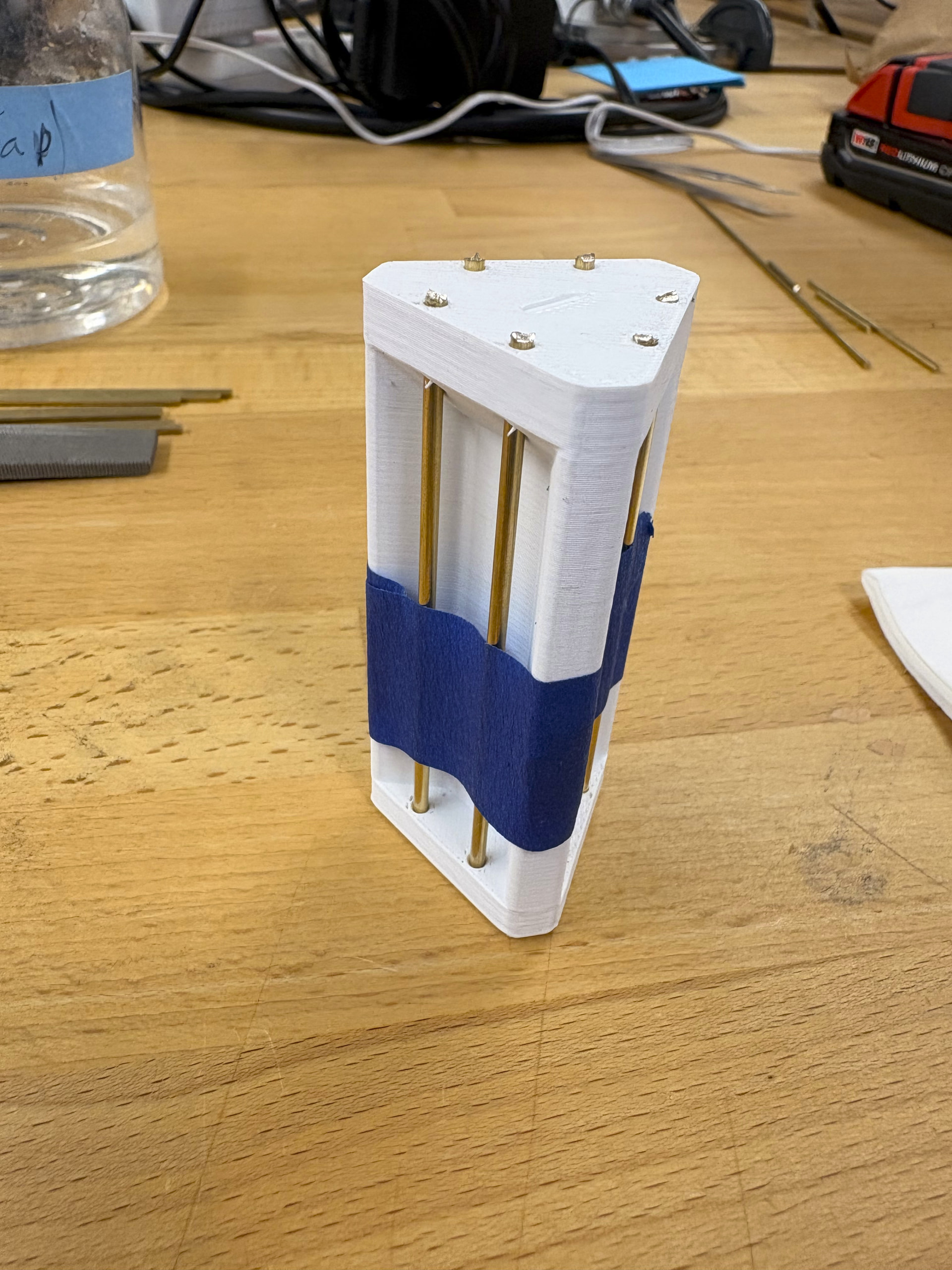
While sanding, the rods would somethings slip out of position so I secured them with tape before proceeding. I used a 120 grit sanding disk I had laying around and dampened the sandpaper with tap water.
I originally only made 6 rods but I would recommend processing a few extra in case a rod bends or is embossed incorrectly in later steps.
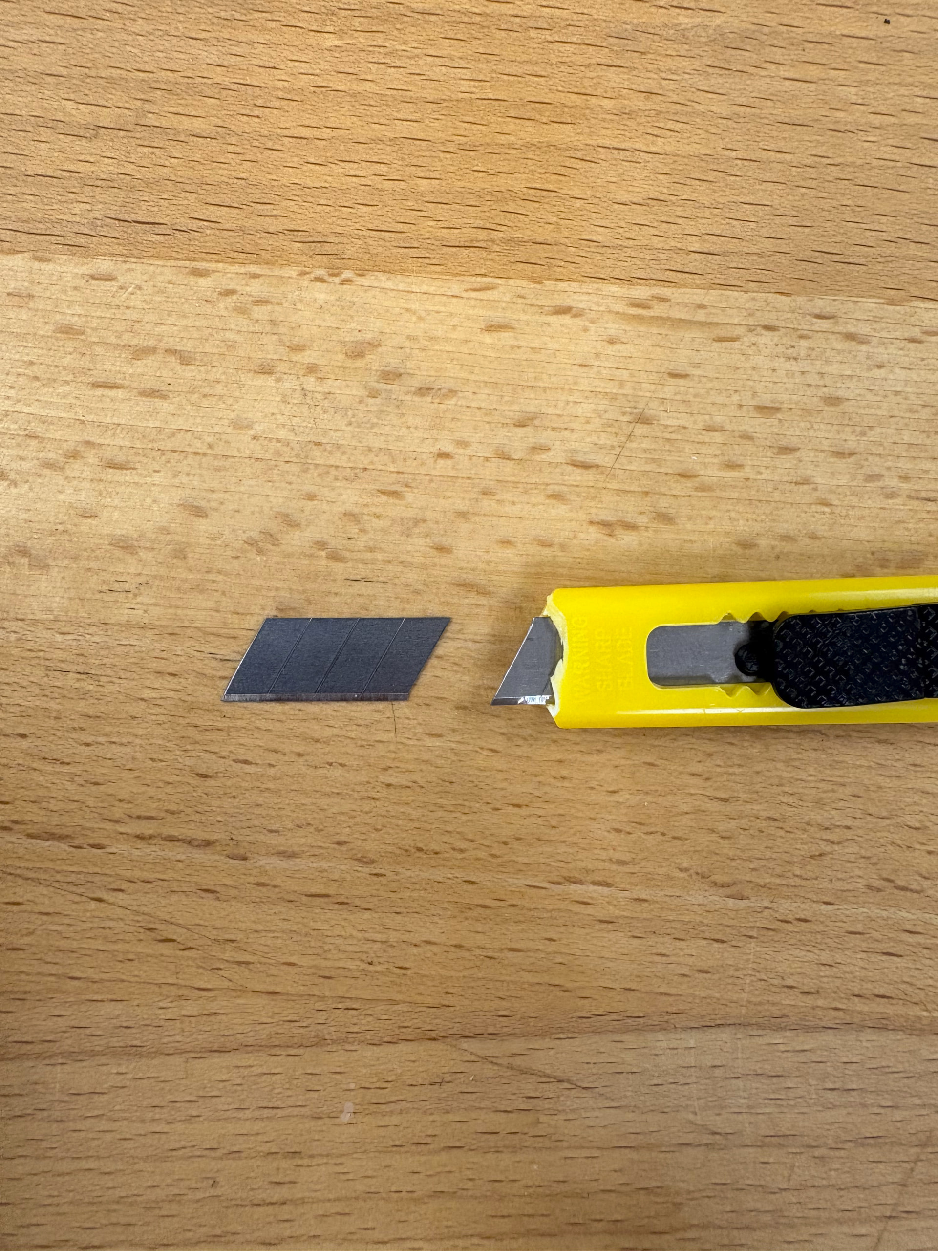
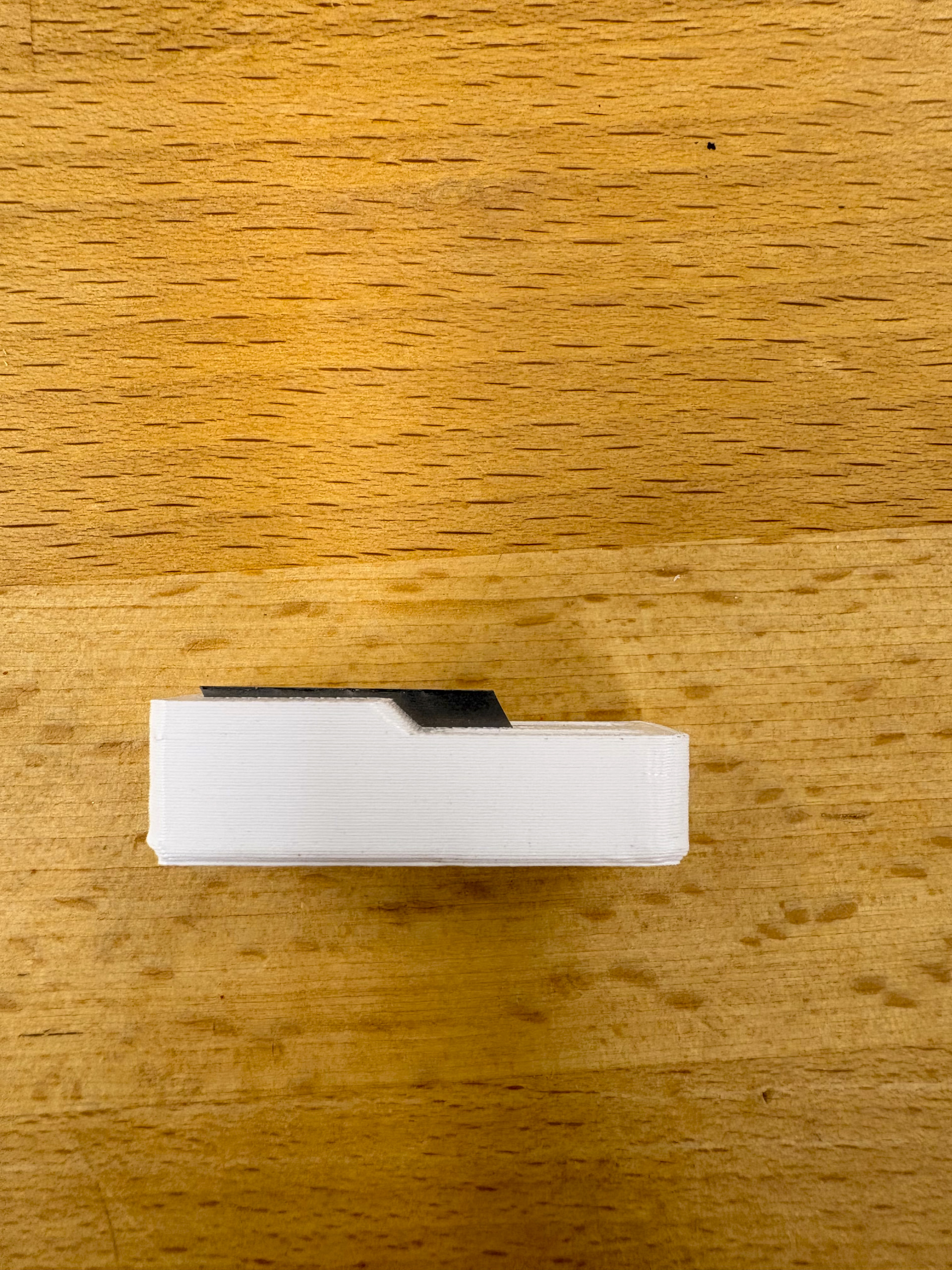
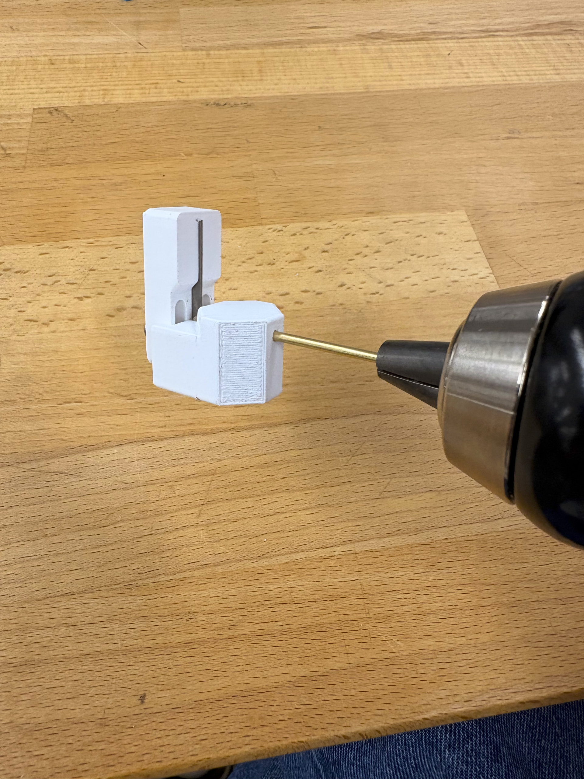
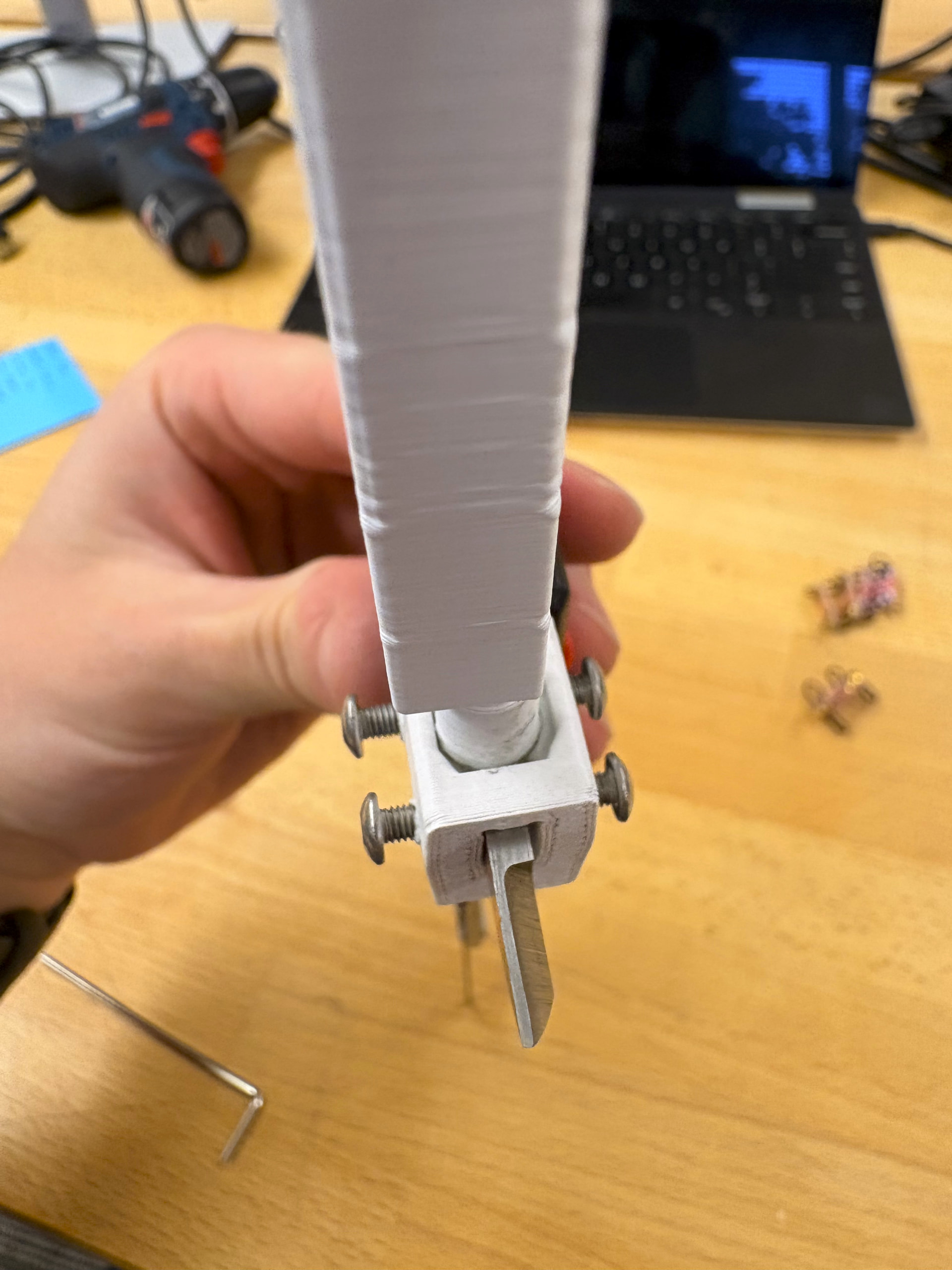
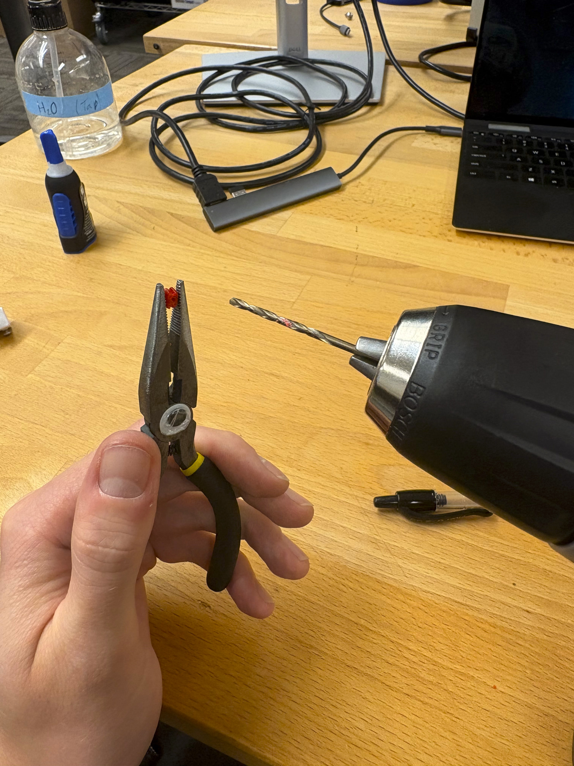
I then used a 2mm drill bit to ensure a snug fit on the rod guild. instead of a 18mm utility knife blade, I used 4 mini utility blades.
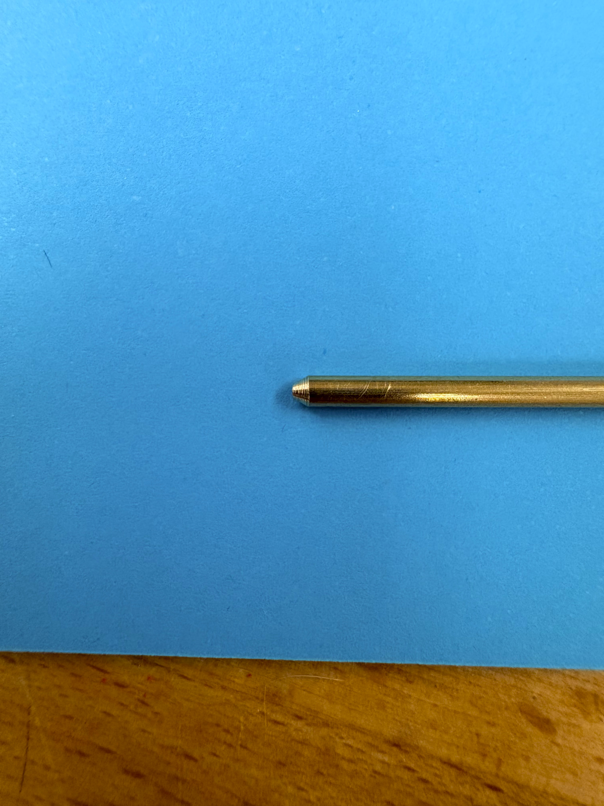
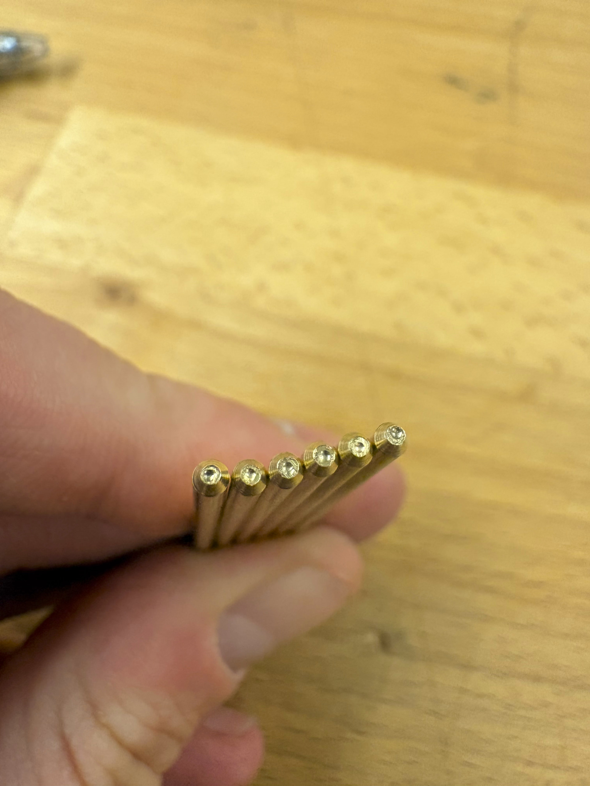
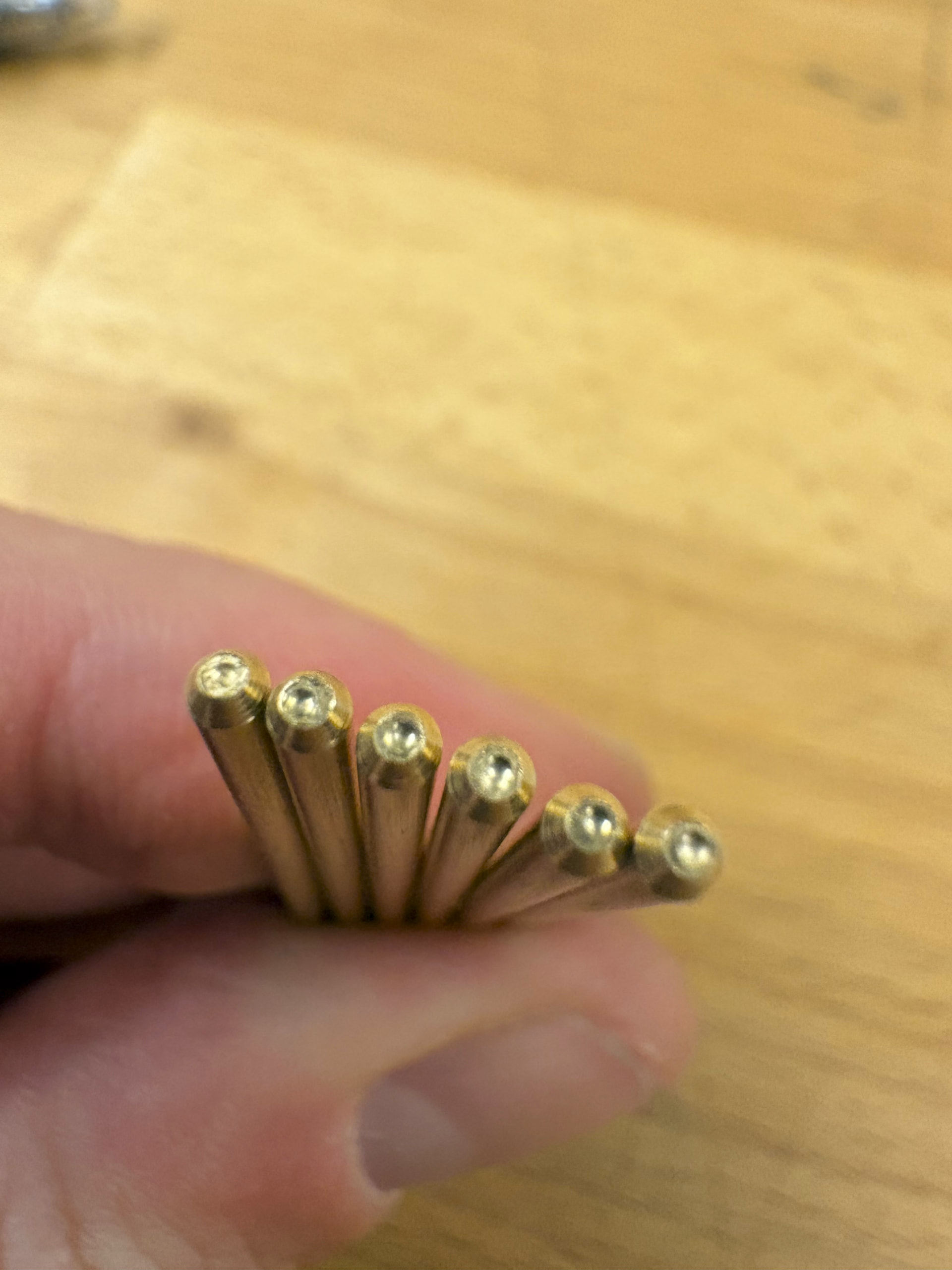
I sacrificed a rod to adjust the sharpening jig to the correct height for the following rods. I then use a sticky note to check that my sharpened rods were consistently sharpened to 1mm diameter throughout the set.
2 Likes
This is really great documentation chris! These kinds of little details are a great resource for folks when they are trying to build a thing
1 Like
Embossing Rods
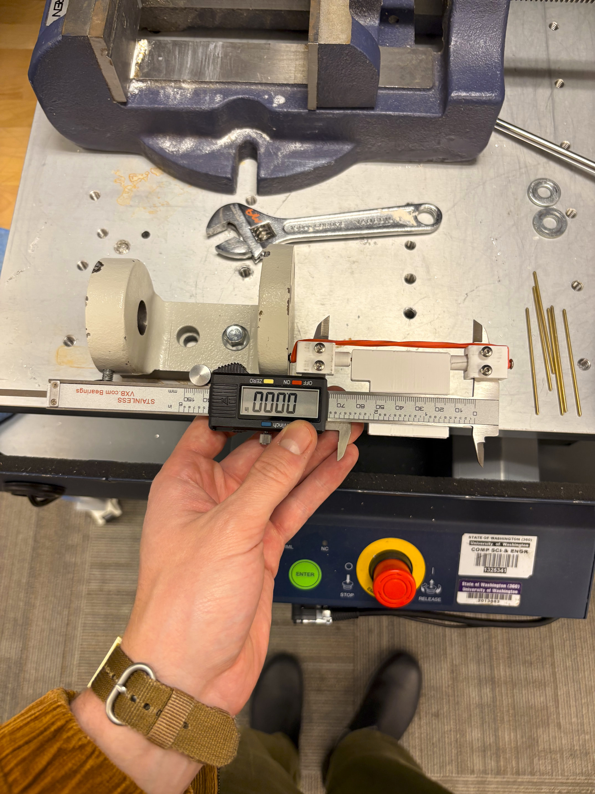
To finish the manufacturing of the ball joint arms, you have to emboss the tips to a consistent depth using a vice, calipers, and a custom rod alignment jig.
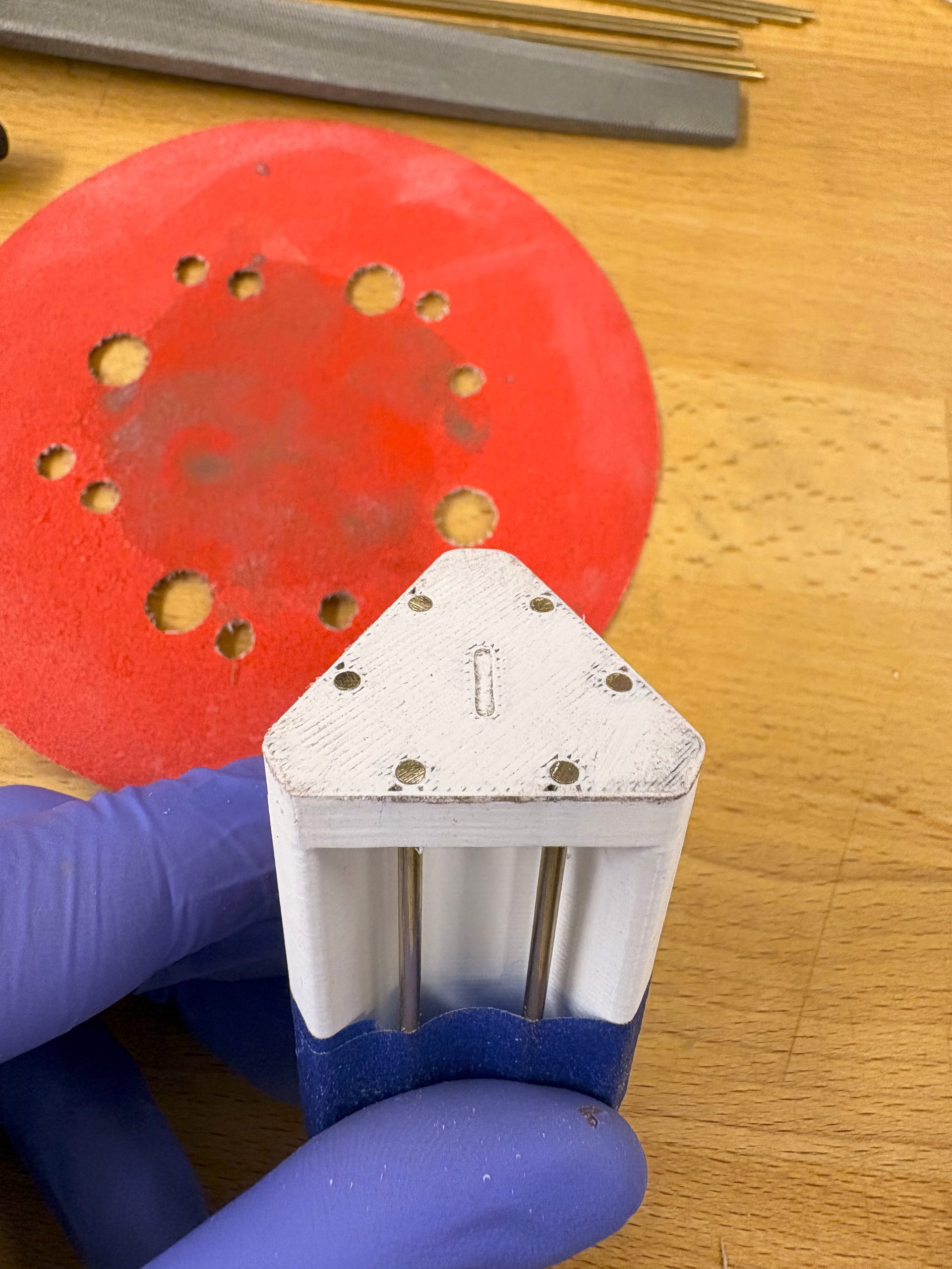
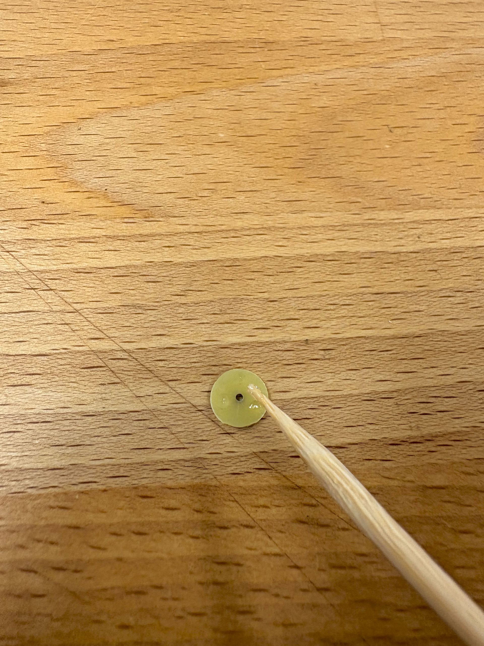
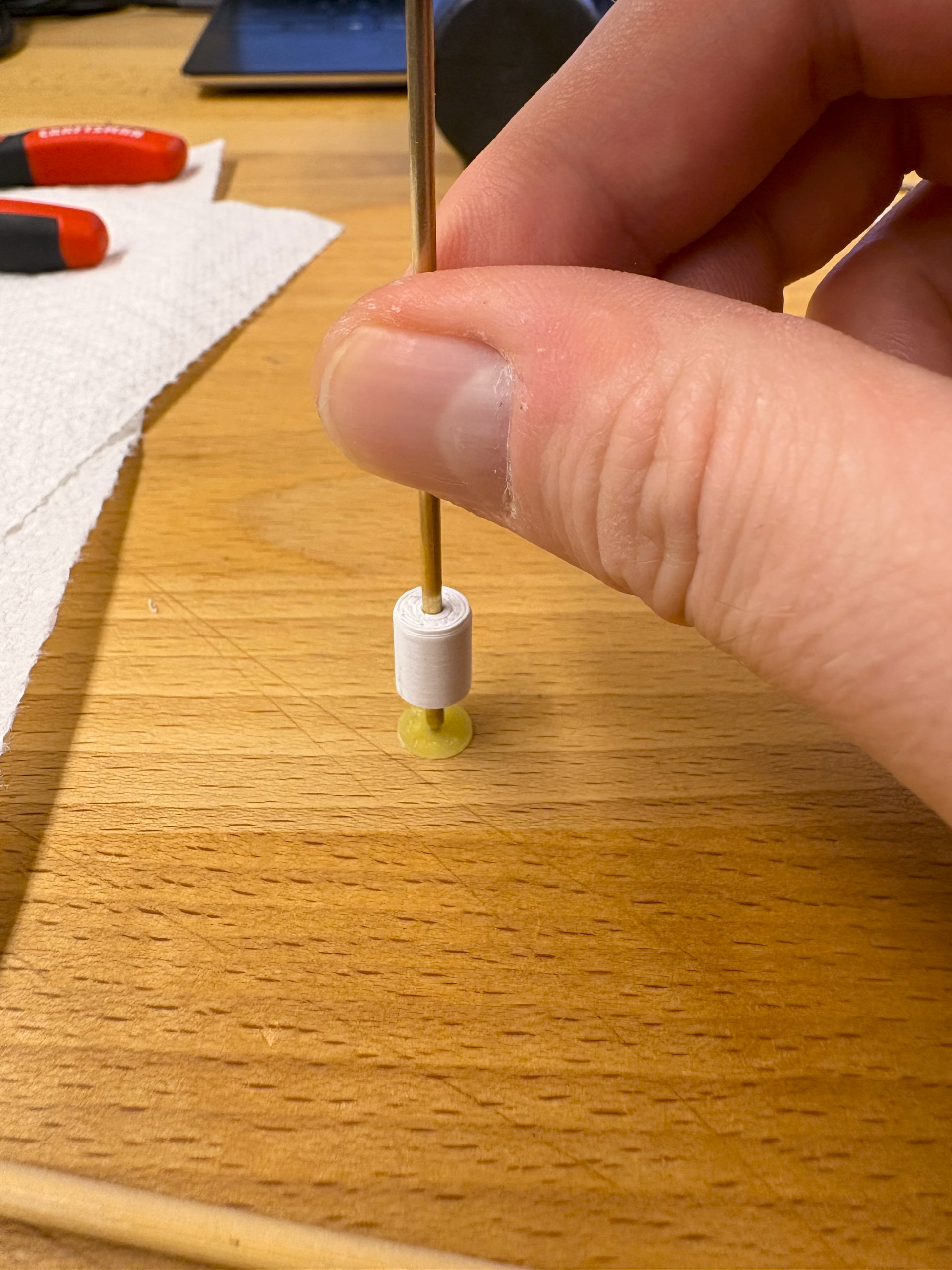
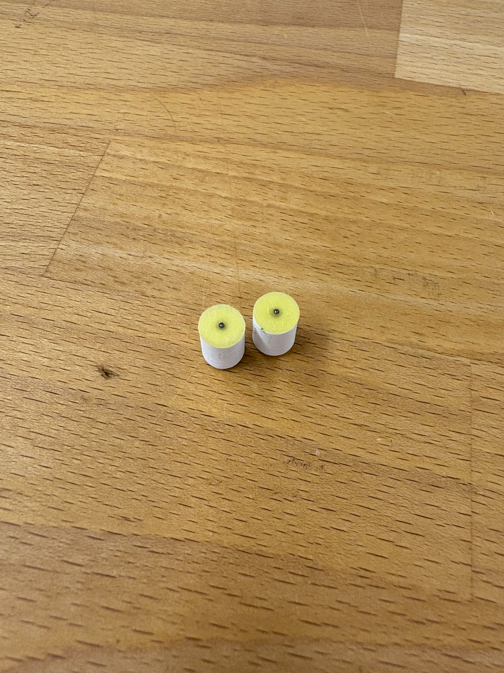
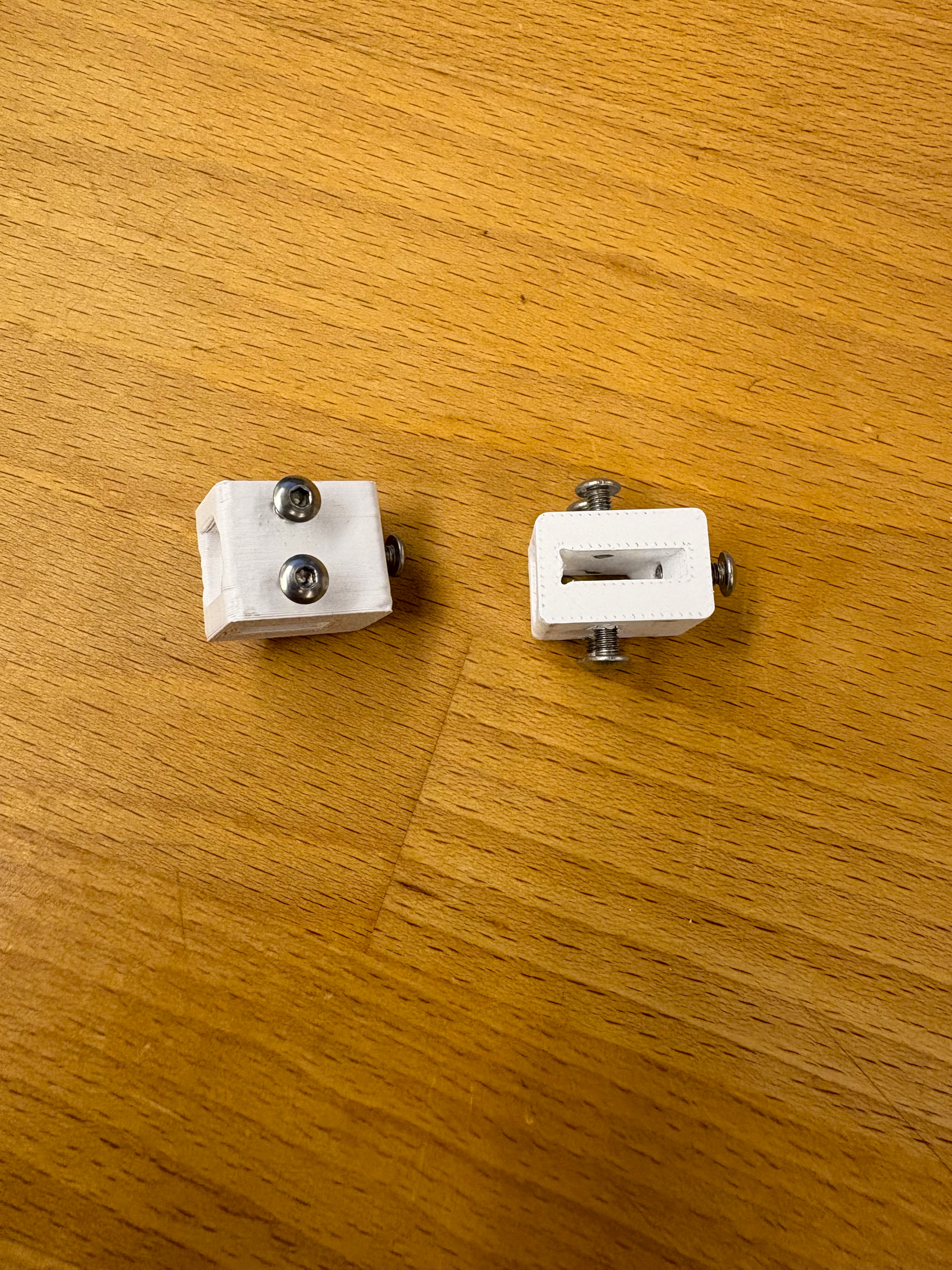
I created the rod alignment rig by gluing the ball alignment disks to the 3D printed rod collects. I used a 2 mm drill bit and a spare rod to friction fit the collects to the rods diameter. I then used a spare sharpened rod to center the disks on the collect and secured them using super glue. (another reason to have spare rods).
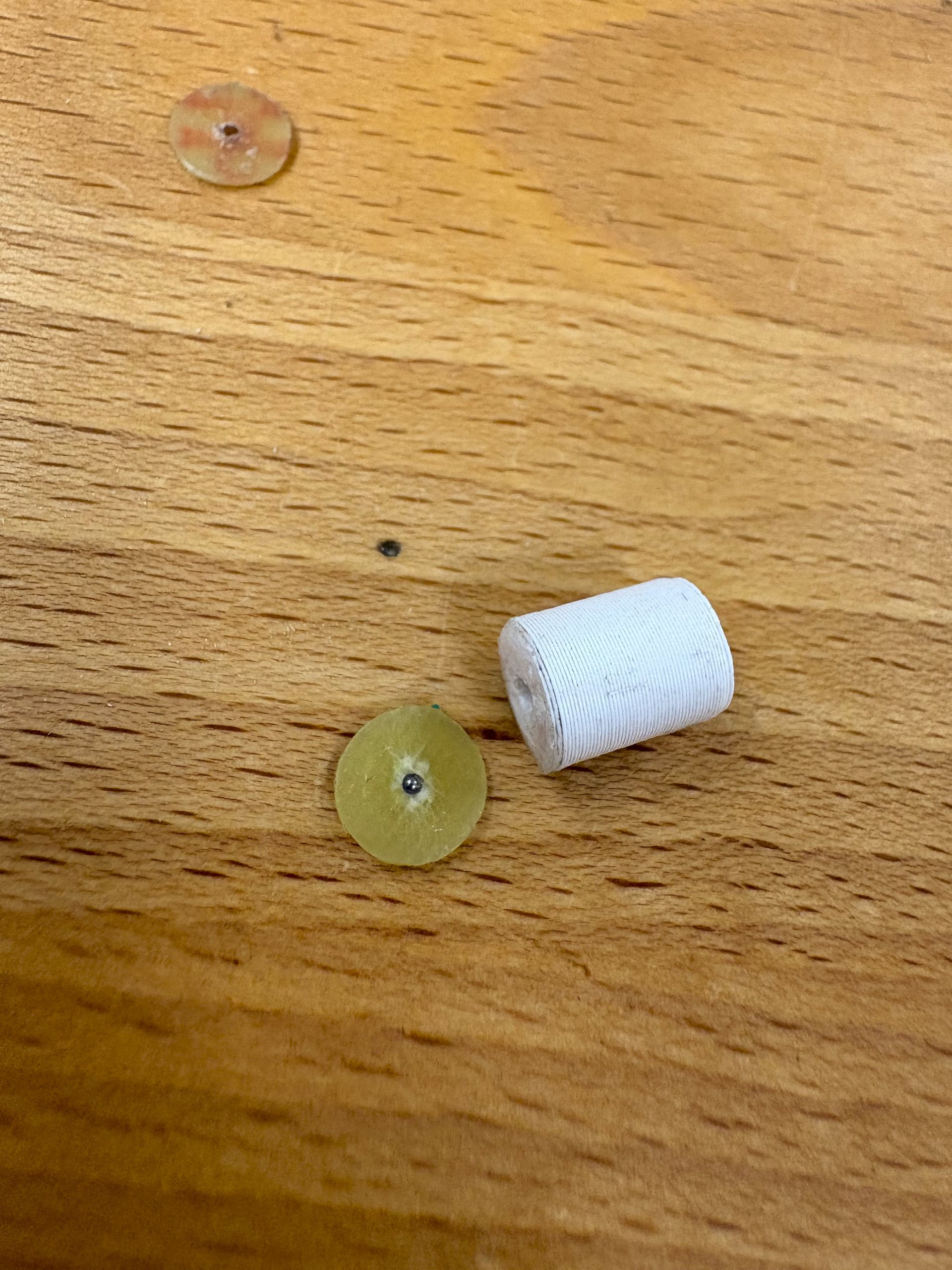
After the glue dried, I inserted a 1mm ball bearing into the disk and sealed it with a small amount of glue. It is important that there is not an excess of glue on the end to ensure that the embossing depth can be constant on both sides of the rod for all rods.
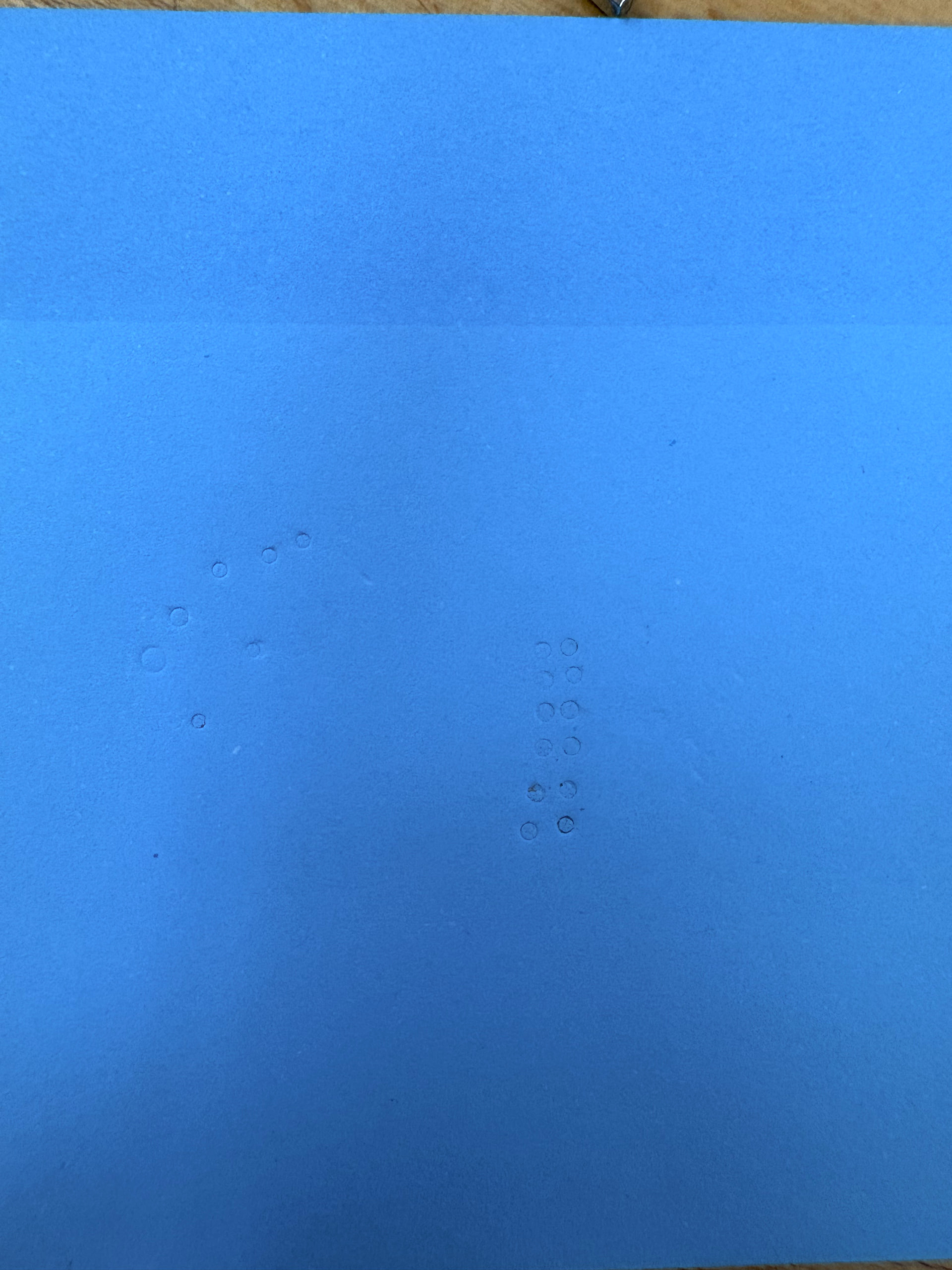
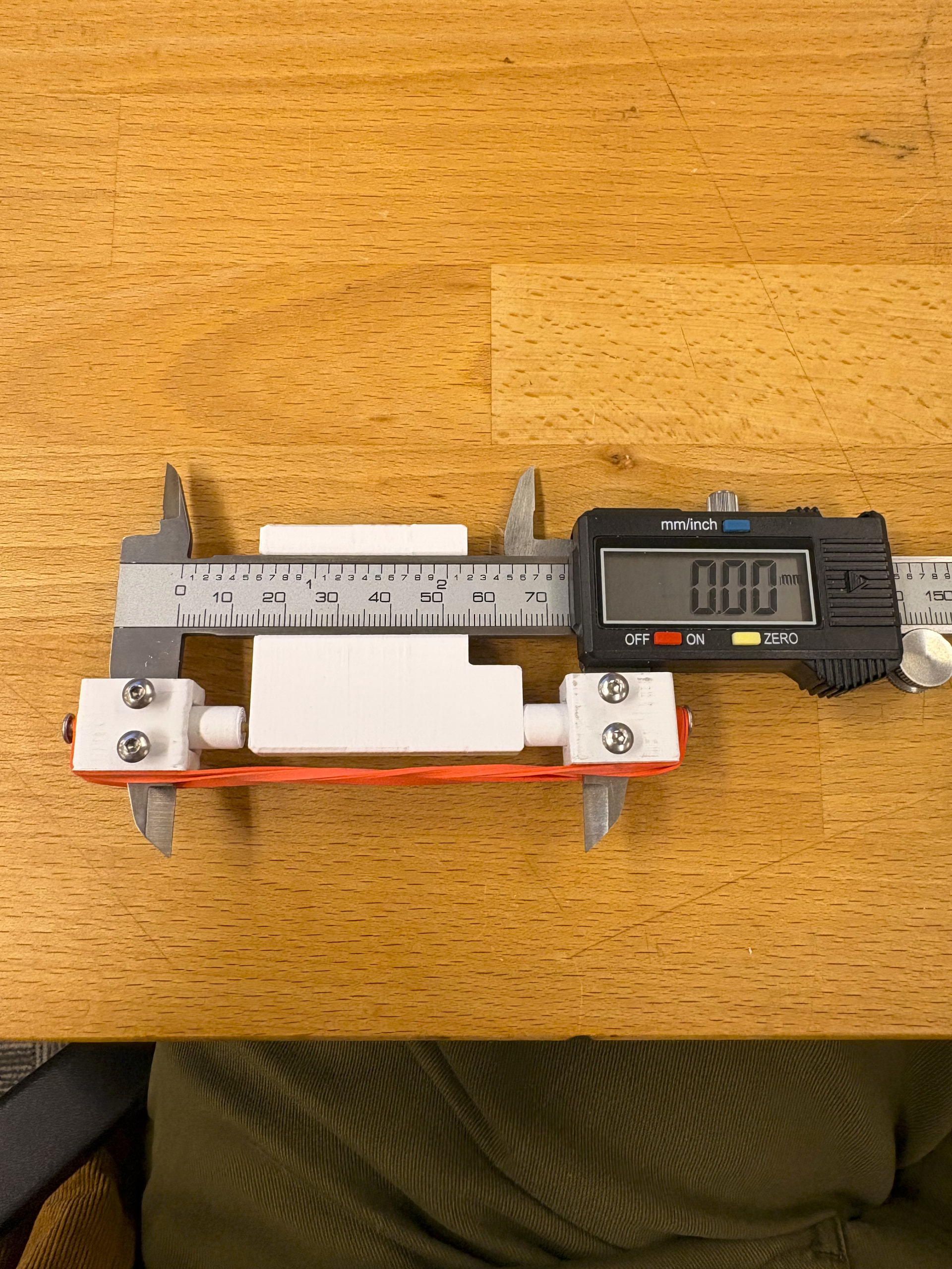
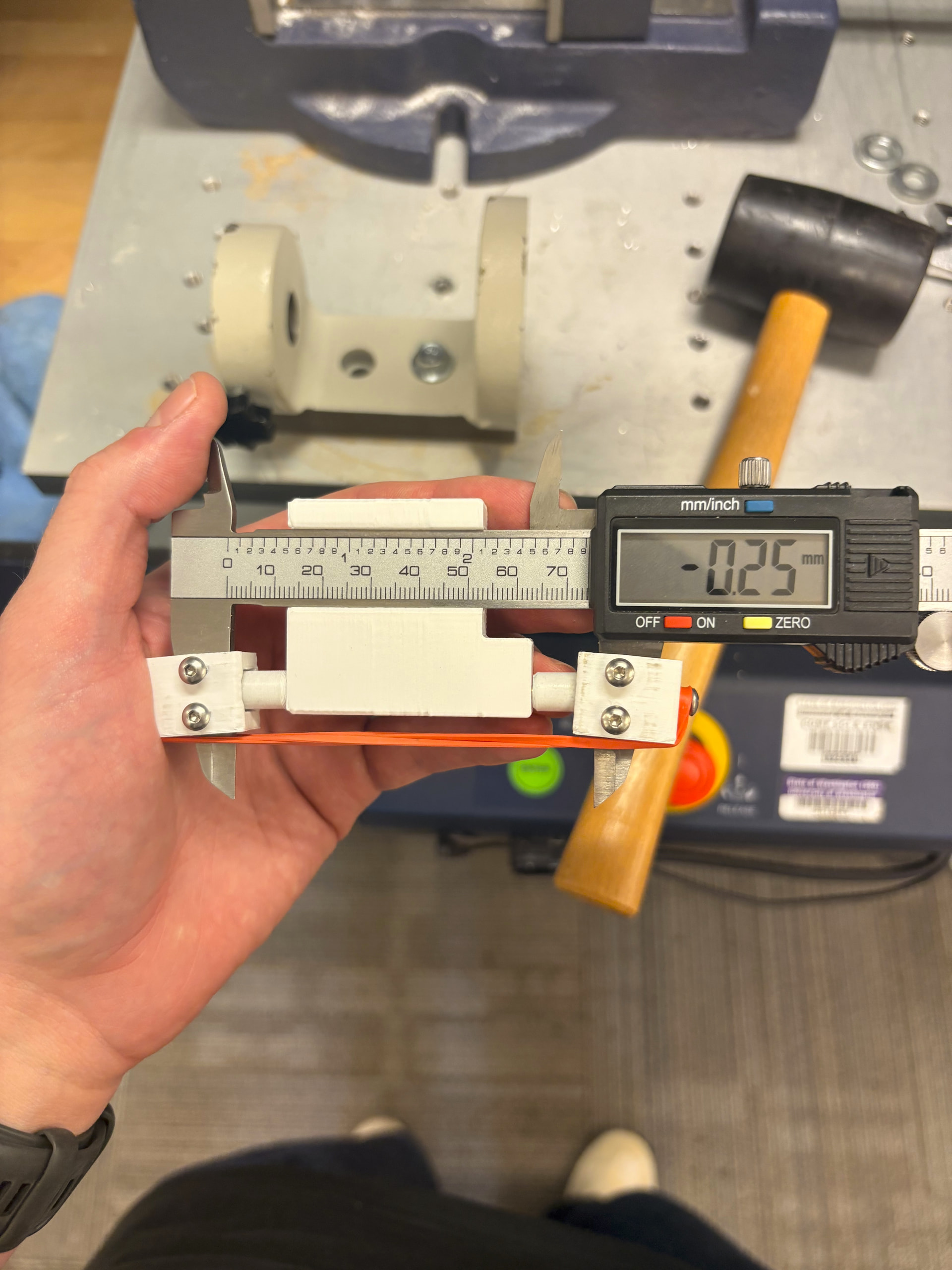
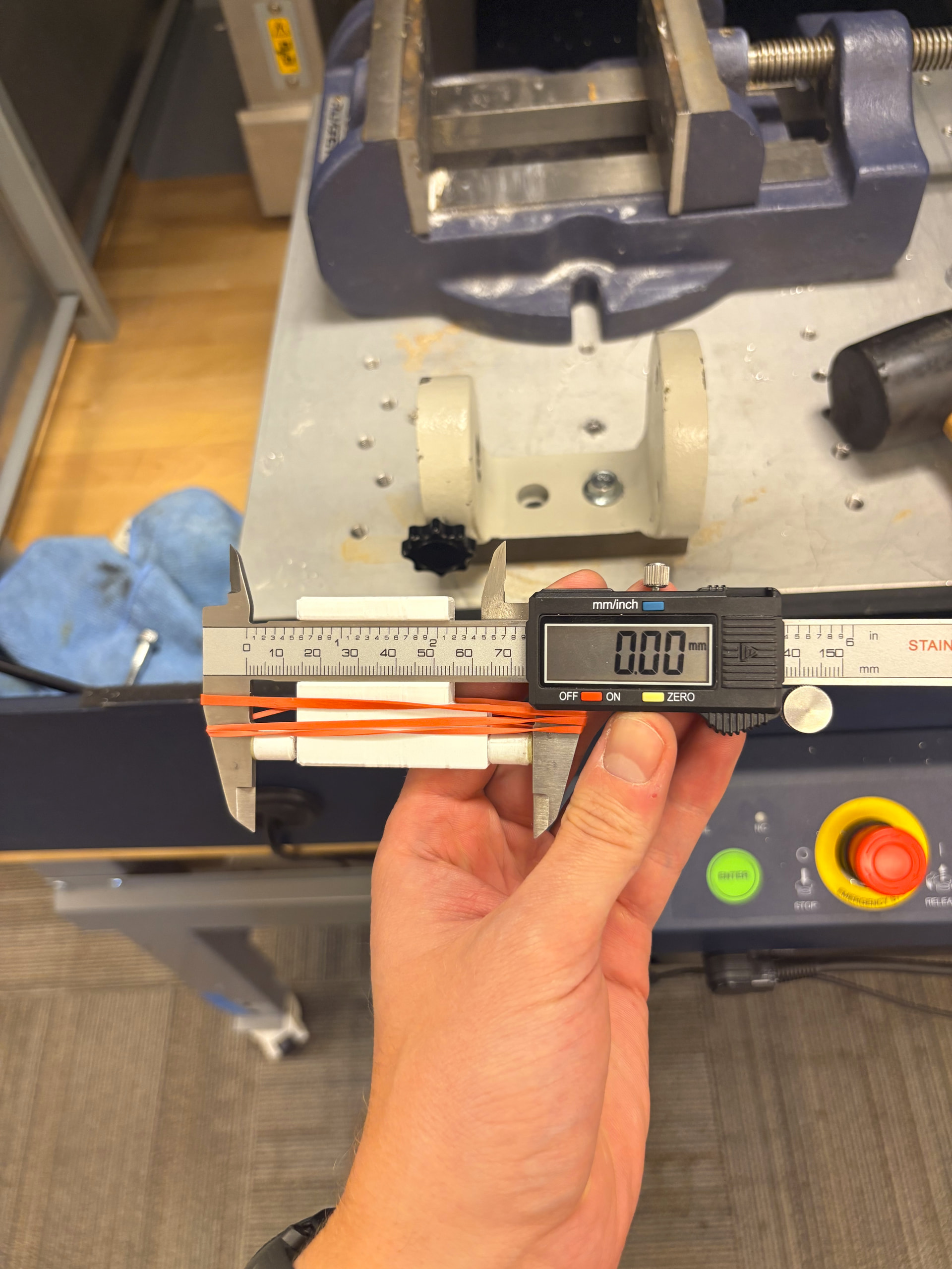
I rigged up a pair of calipers with the rod guilds. Minor detail: but I did not see a rubber band in the BOM. A rubber band is used to keep tension on the rod to maintain an active depth reading. I zeroed the calipers and then used a mallet to gradually emboss the rods to a depth of around 0.25 mm (0.125 mm on each side). After I reached 0.25 mm, I zeroed the calipers again and continued to manufacture the other rods till the calipers read 0.00 mm.
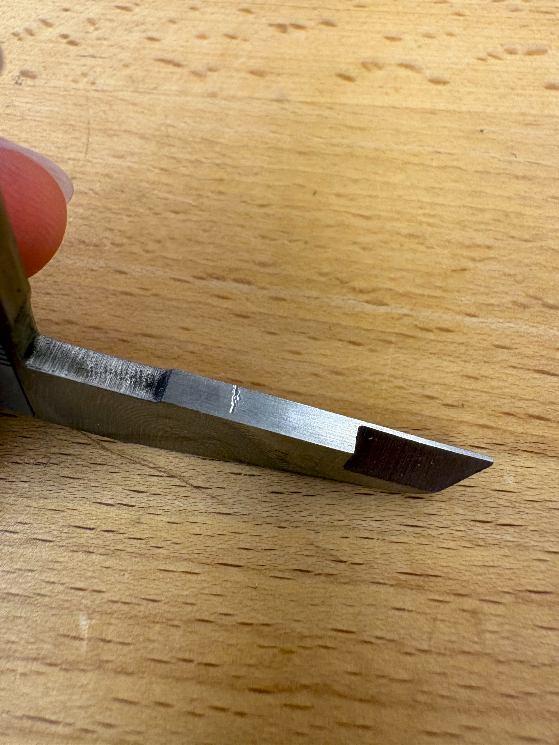
It’s important to note that after processing the rods, there will be small indents in the caliper’s arms. I would recommend using a caliper that you do not care too much about.
I was having issues with my alignment disks detaching from the 3D printed rod collects during this process. I tried different glues and using extra glue on the edges of the rod collects but still had this issue. I would recommend having multiple rods and alignment disks prepared in case this happens. I ordered 5 of the ball alignment disk PCBs from jlcpcb and ended up using all of them.
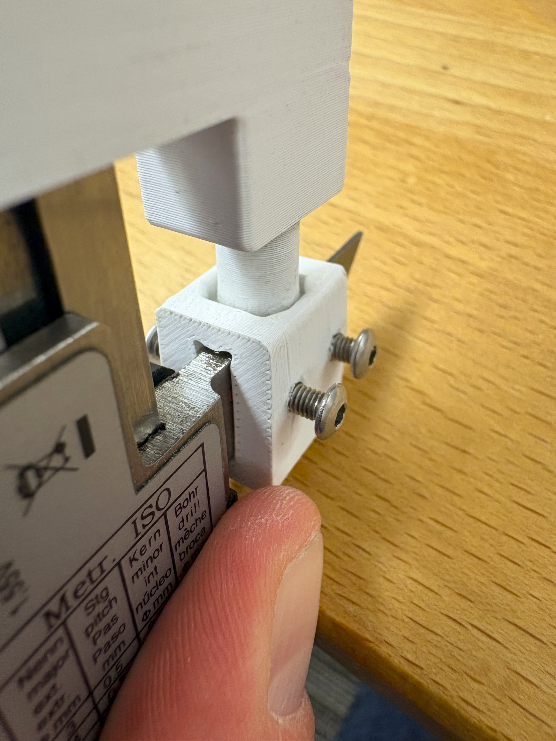
I noticed that it was actually the rod guilds that attached to calipers arms that were causing the disks to fall off. I tried filing them to sit flush with the caliper arms and got better results. I also tried a few rods without the arm guilds. This worked but was slightly awkward because I had to rest the calipers at an angle.
I was quite impressed with this DIY process for embossing the rods. Even though this was the most finicky step, the rods that I made were consistent and the process was very repeatable. My biggest tip would be embossing a couple extra rods and to check for depth consistency as you go.
1 Like
Ball Joint Arm Construction
Now that I have the rods processed, the last step before the mechanical assembly is to make the 3 ball joint arms. This process is straightforward and used the BOM on the StepWiseDocs to order my components.
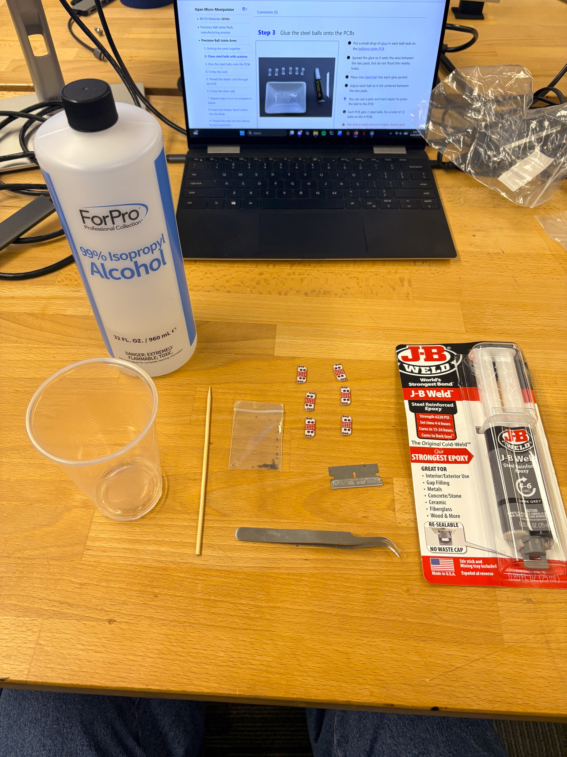
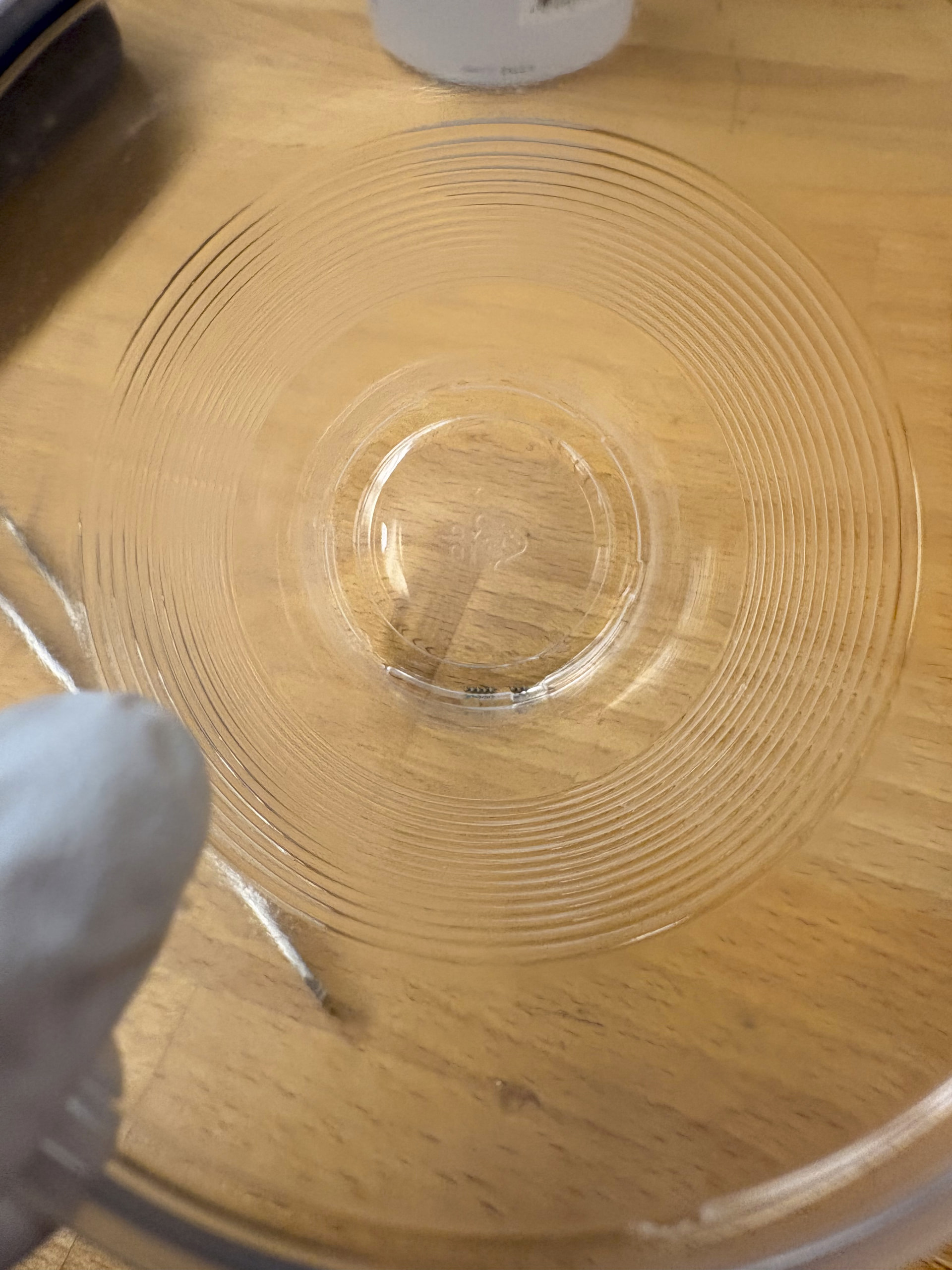
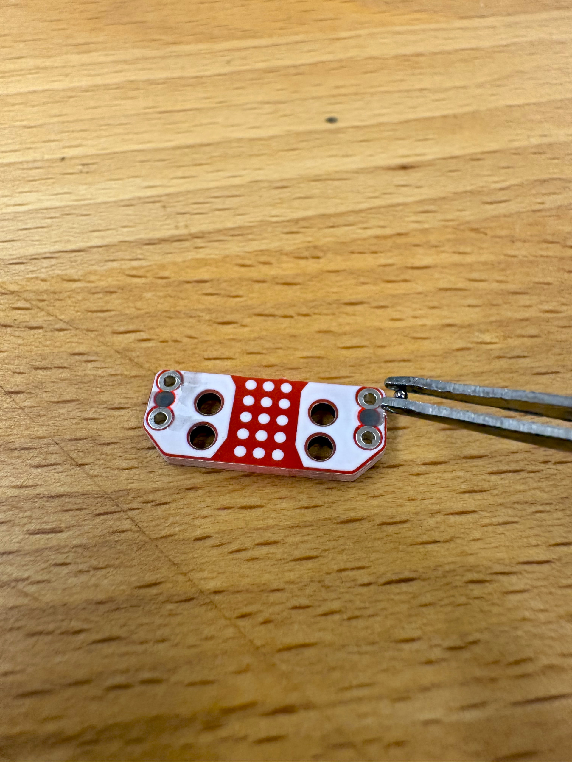
I first soaked the ball bearings in 90% Isopropyl alcohol to remove any oils and grease left behind by the manufacturer and any fingerprints to ensure strong adhesion. Once the ball bearing dried, I used gloves and clean blunt tweezers to handle them.
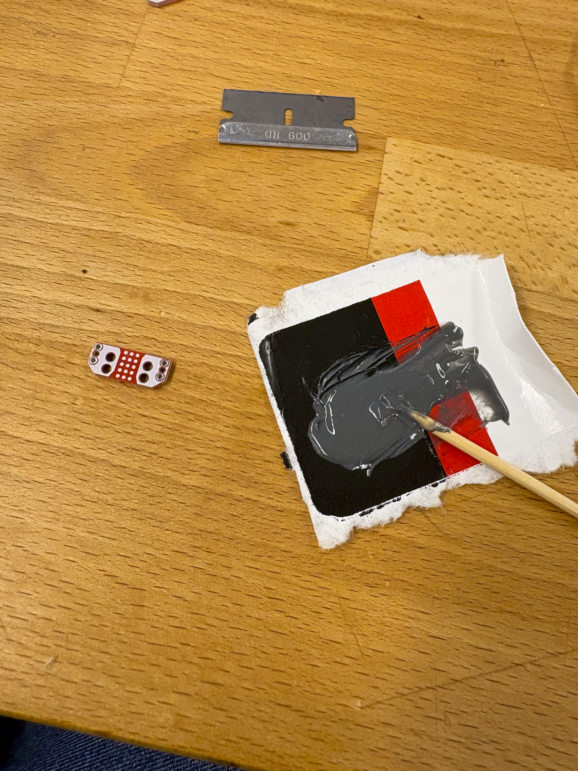
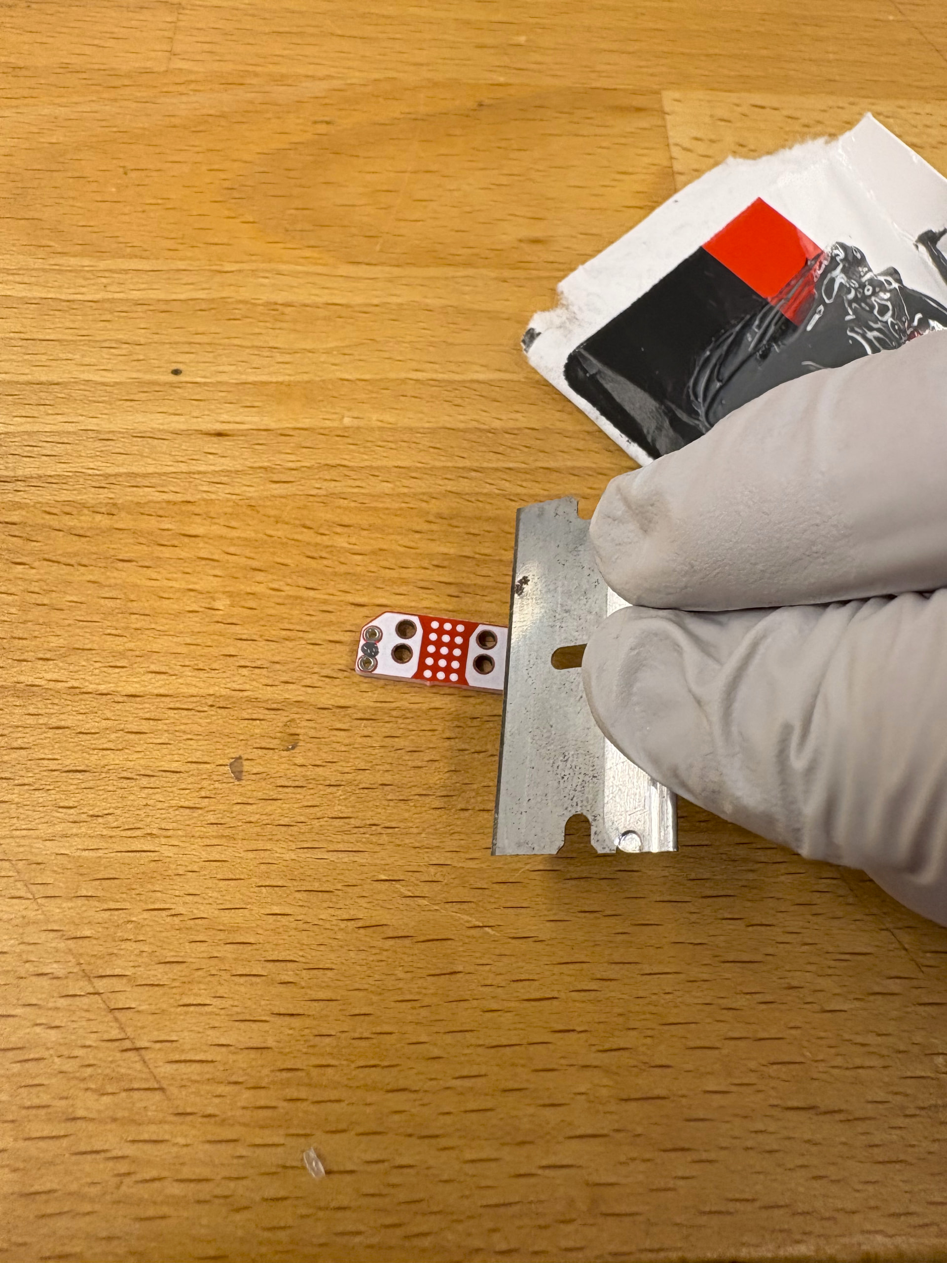
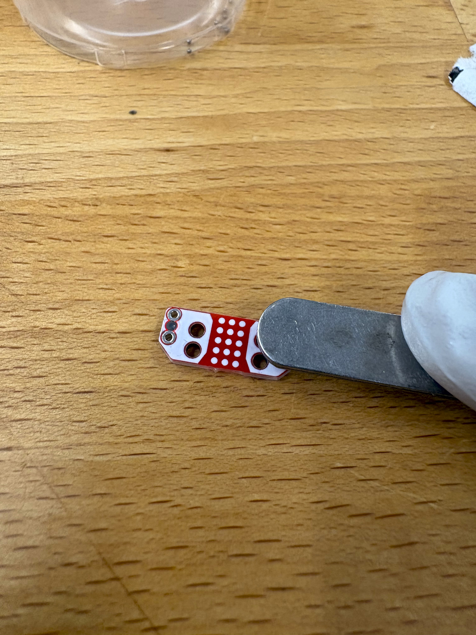
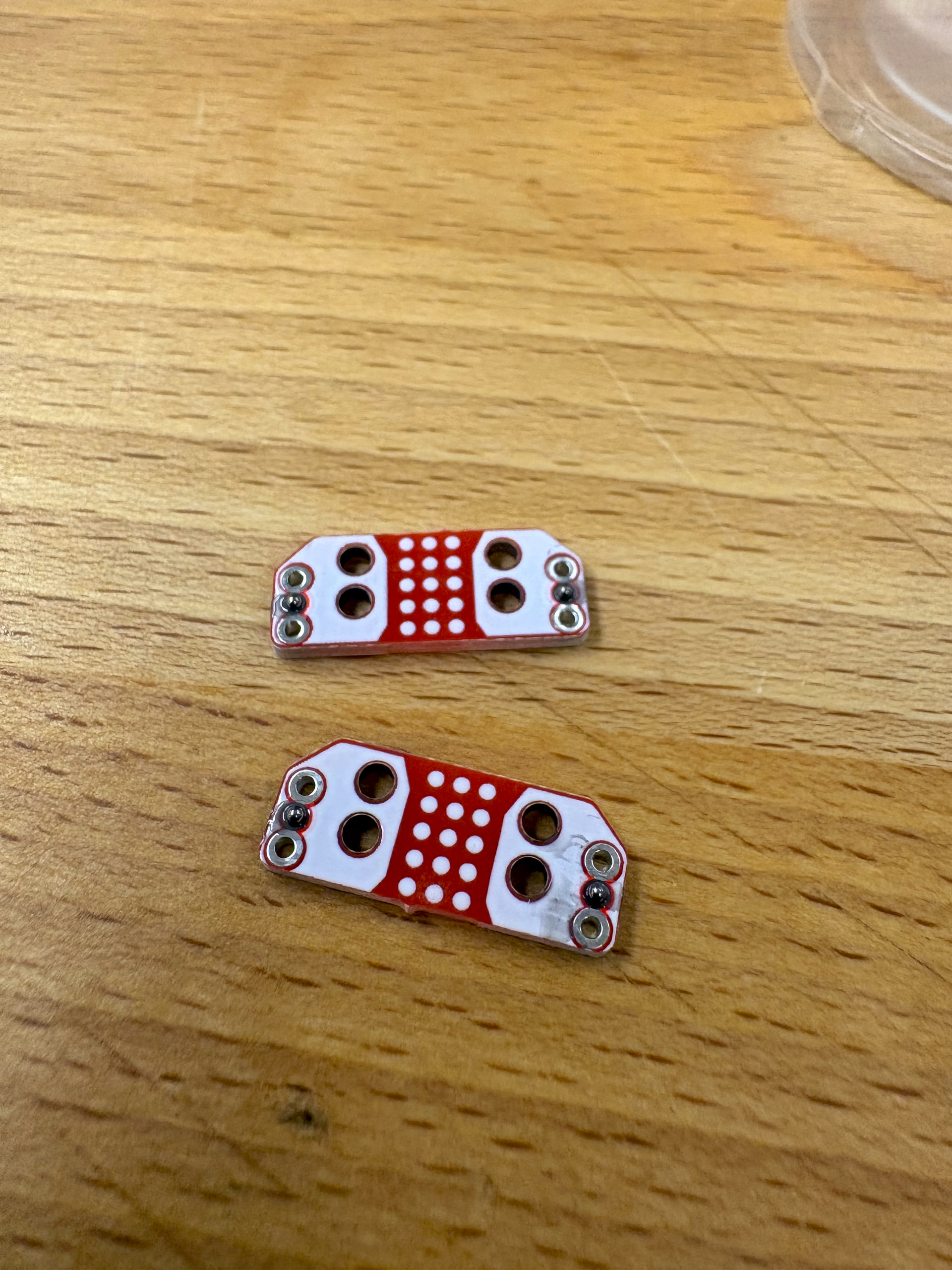
I used JP weld steel reinforced epoxy as my adhesive. JP weld is not on the StepWiseDocs BOM but this is what was used in the original YouTube tutorial. After I mixed the two parts of the epoxy, then I added a small amount to the end hole on the PCB ball joint plate. I scraped away any excess with a clean razor blade and inserted the ball bearing using the tweezers. I then pressed down on the ball bearing using the back of the tweezers to ensure a snug and accurate placement. Then I let these cure overnight.
I would recommend making a couple extra PCB plates. Once I started attaching the rods, I had 2 plates that had their ball bearings detach.
I would also recommend going through the build guild and finding all the steps that require gluing and doing them all at the same time to be as efficient as possible. This includes the rod collects, PCB plates, and magnets to the ball joint horns.
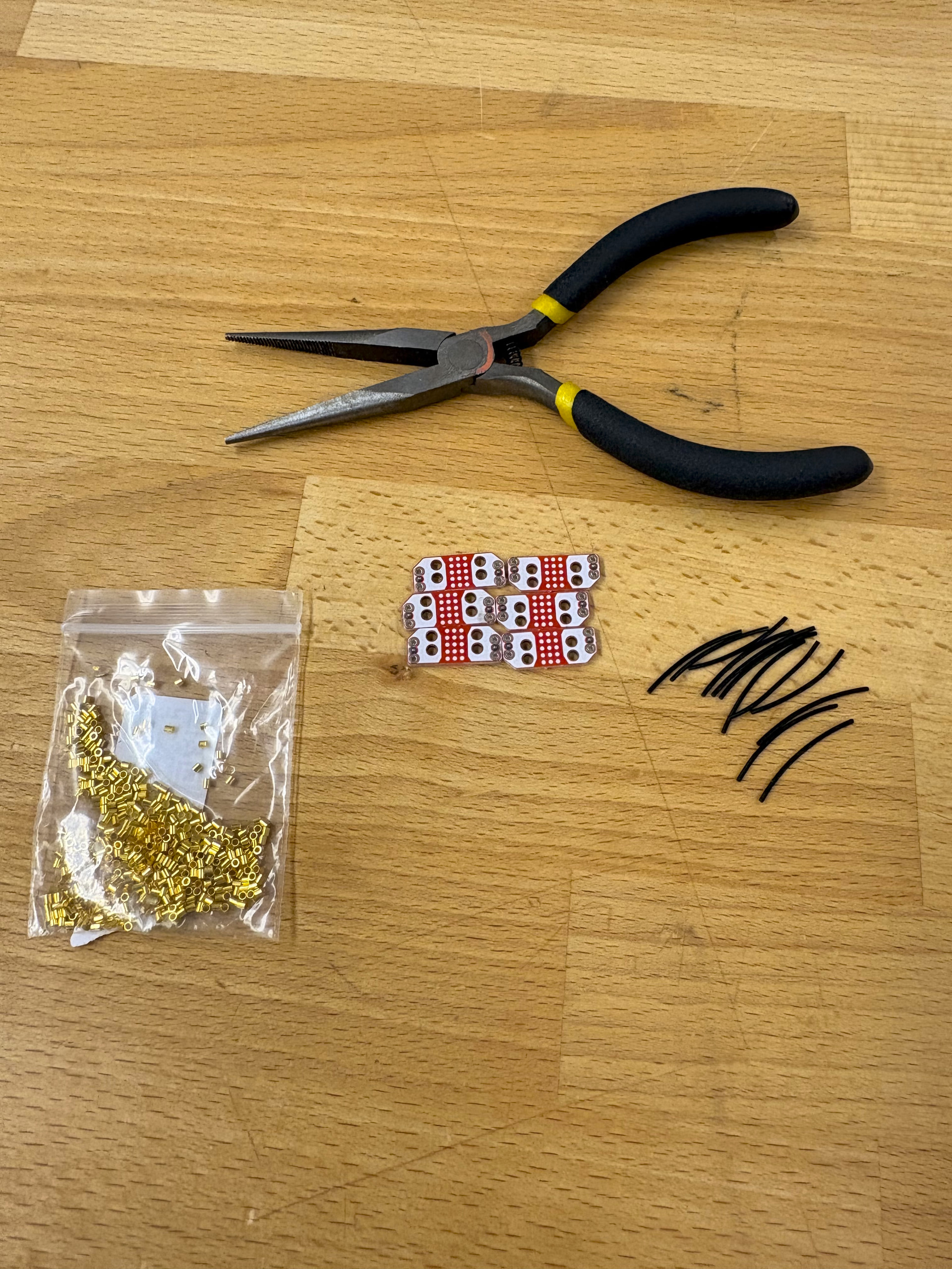
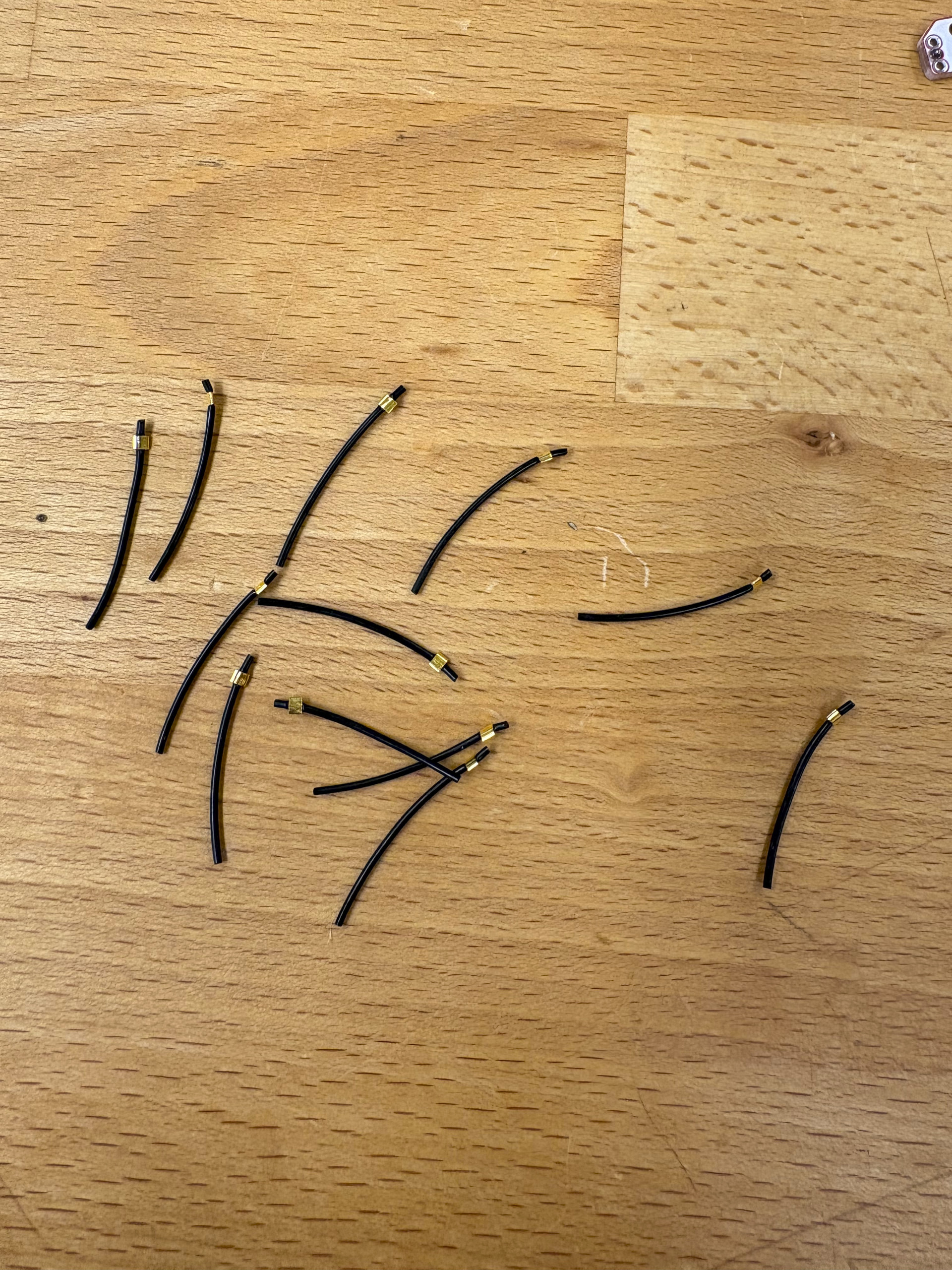
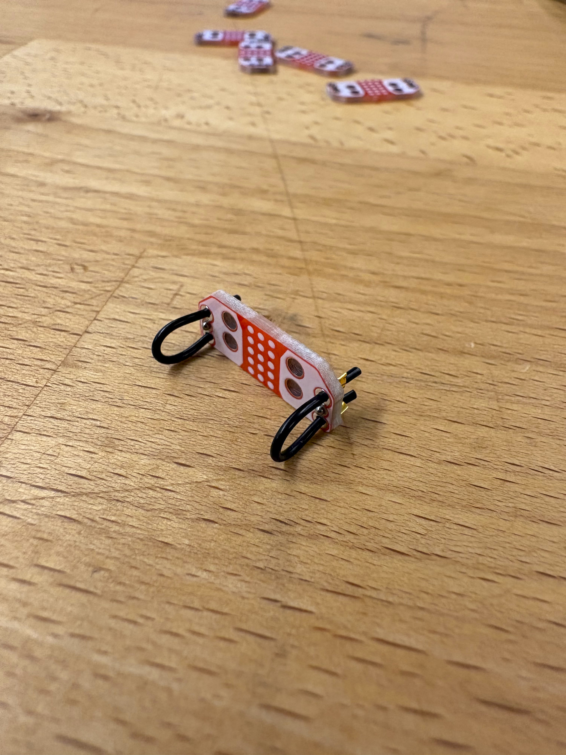
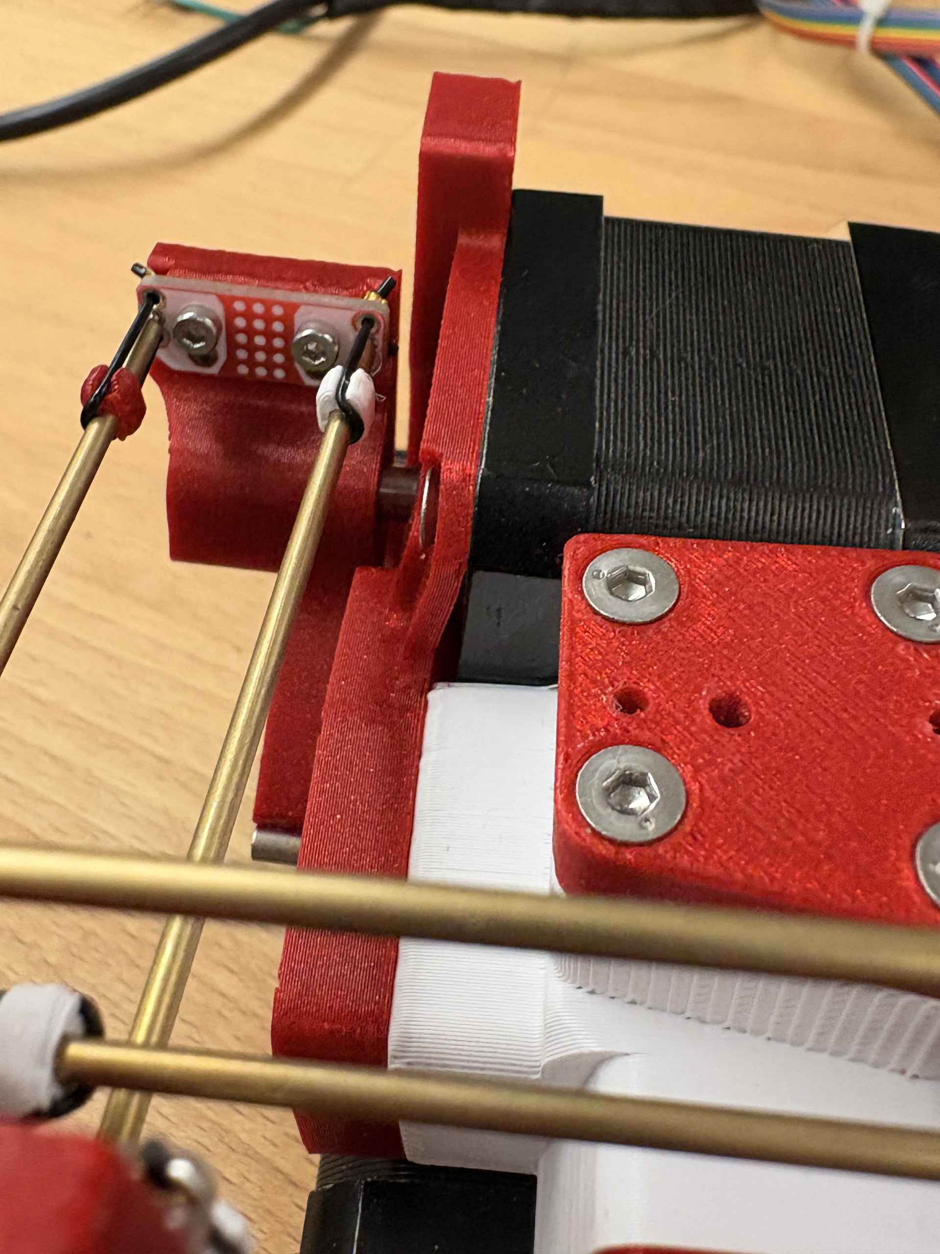
Once the plates had dried, I cut 25 mm sections of the PU cord and attached them using jewelry crimping beads and pliers. It’s important to leave about 1 mm of PU cord on either side of the beads so they don’t slip out under tension.
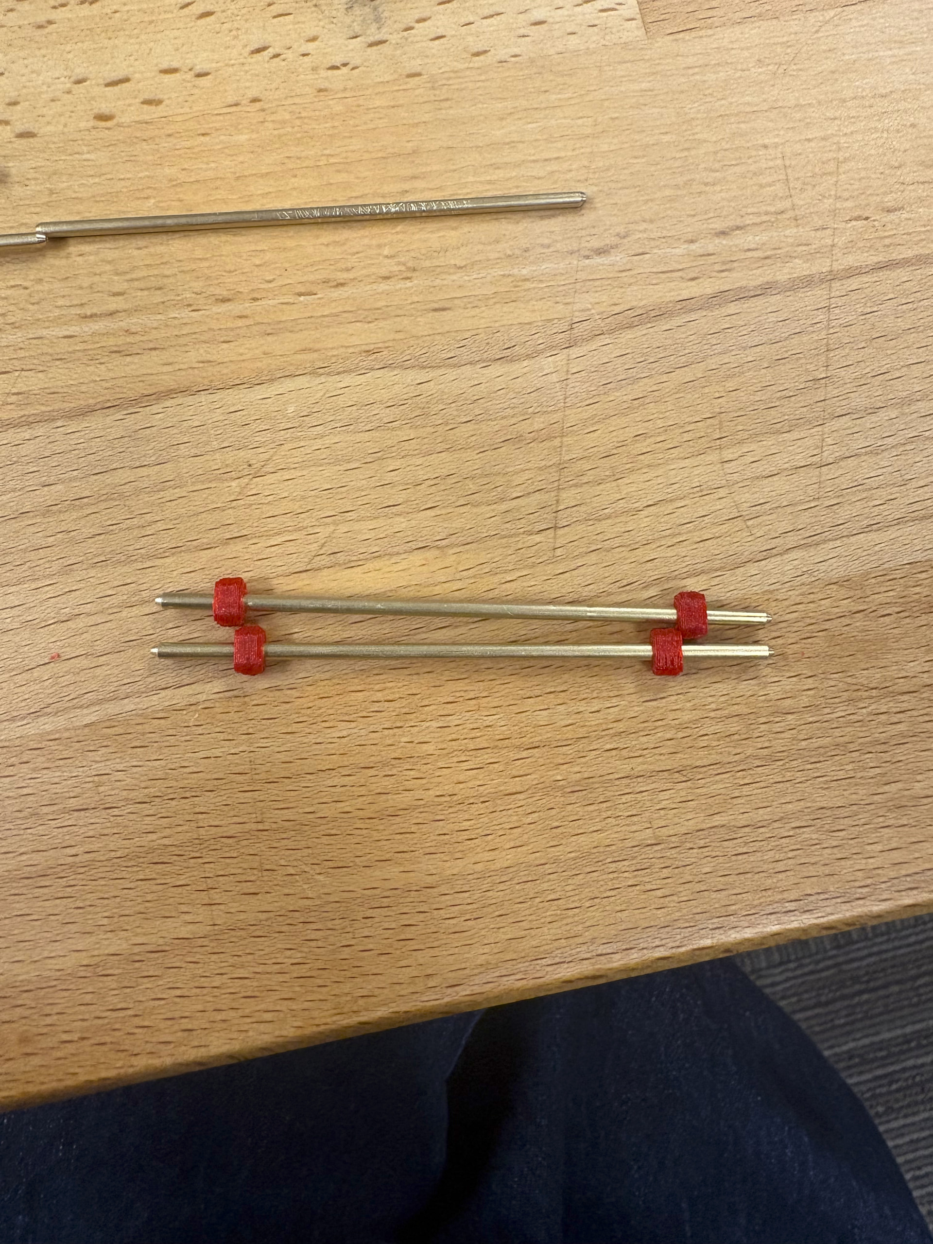
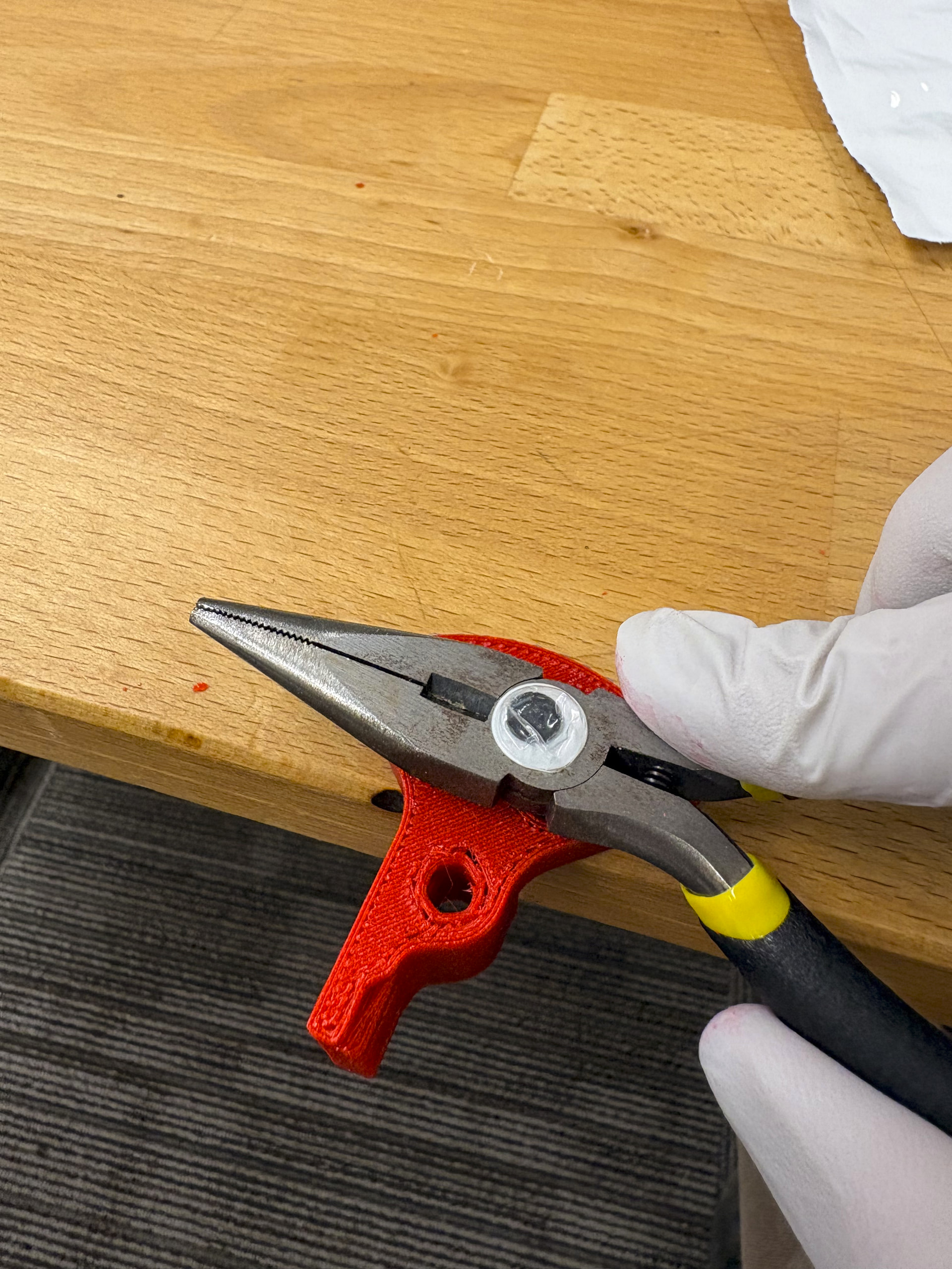
I then added the rubber band collects onto each rod. I had to use pliers and a 2 mm drill bit to wide the collects to get them to fit on the rods. I would recommend printing extra rubber band collects. I found it very easy to over widen the hole on the collects which caused them to slide down the rods when under tension.
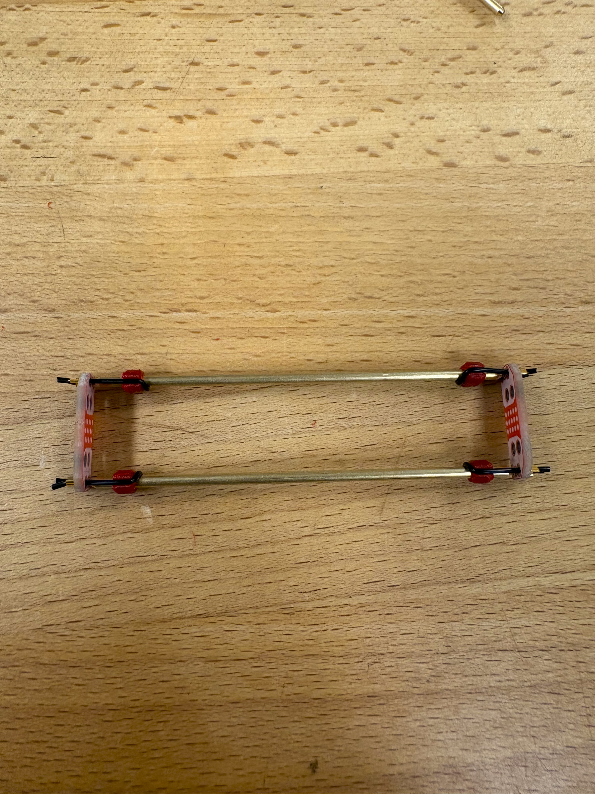
Both build guilds I followed attached the rods to the ball joint plates at this point. I would recommend doing this just to test that the ball joint connections and rods fit as expected. But during the full mechanical assembly, I found it much easier to attach the ball joint plates to the horns and platform with the rods detached from them.
I found it easiest to attached the rods to the joints by initially moving the rubber band collects to the edge of the rod. Then inserting the rod on the joint and tightening the rubber band collects so that each connection has similar tension. Pliers and tweezers might be useful here.
1 Like
Mechanical assembly
Now that the ball joint arms are complete, I am ready for the full mechanical assembly.
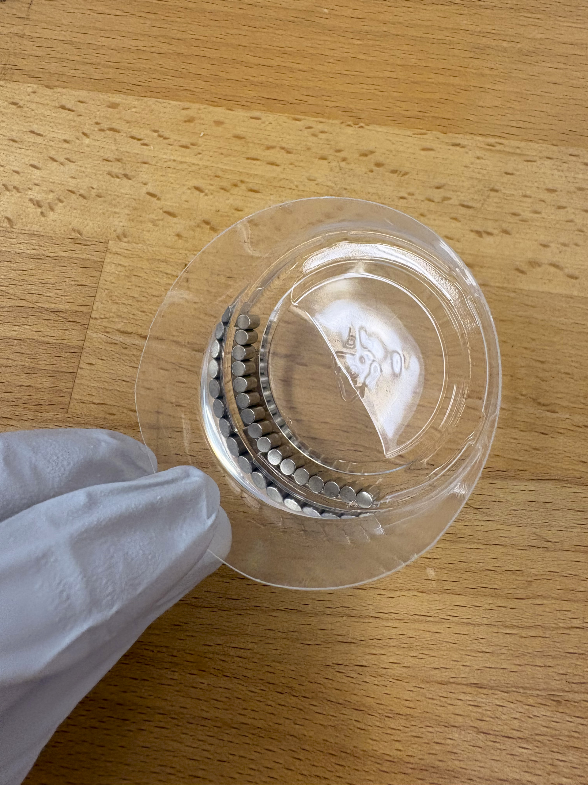
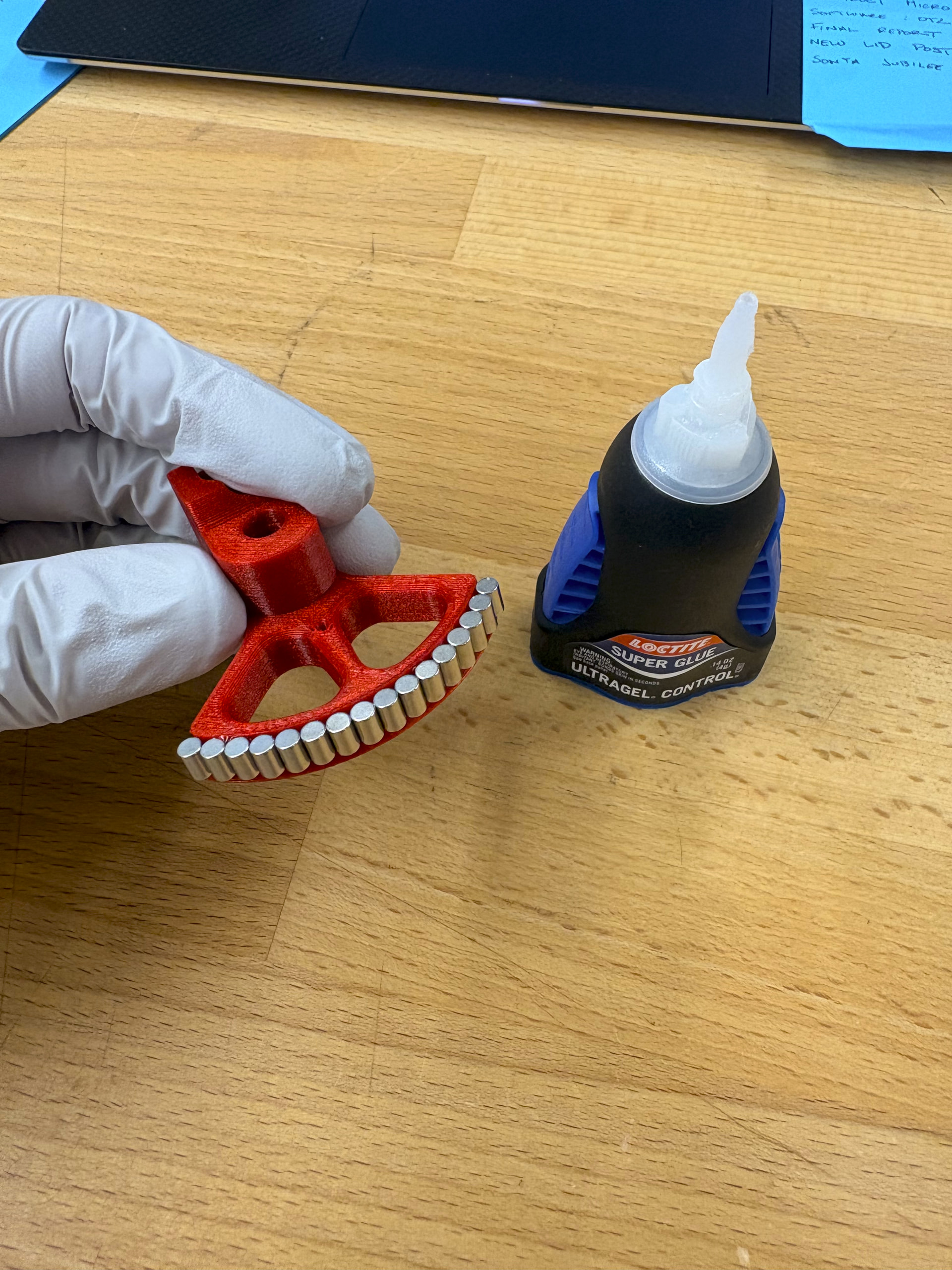
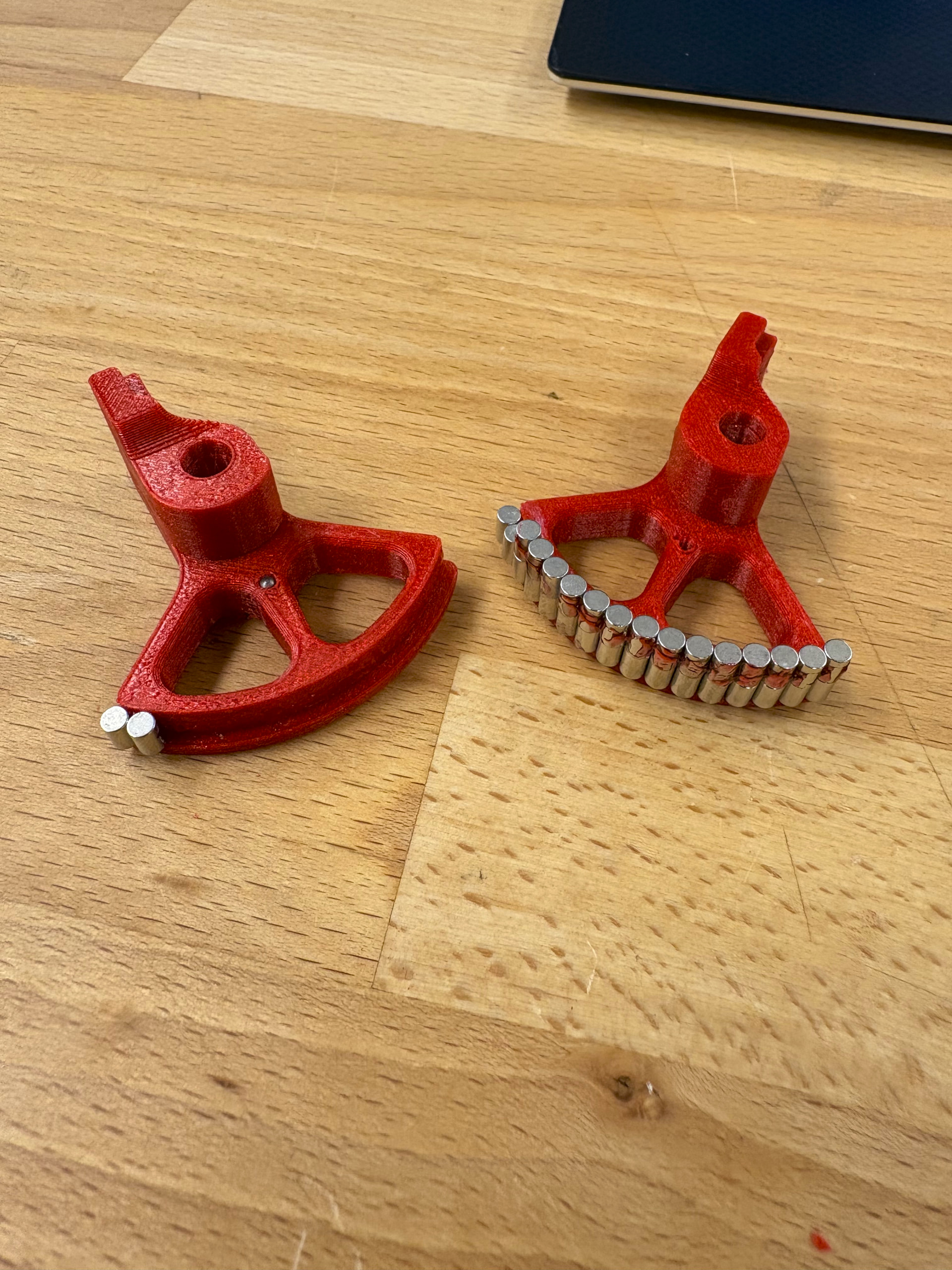
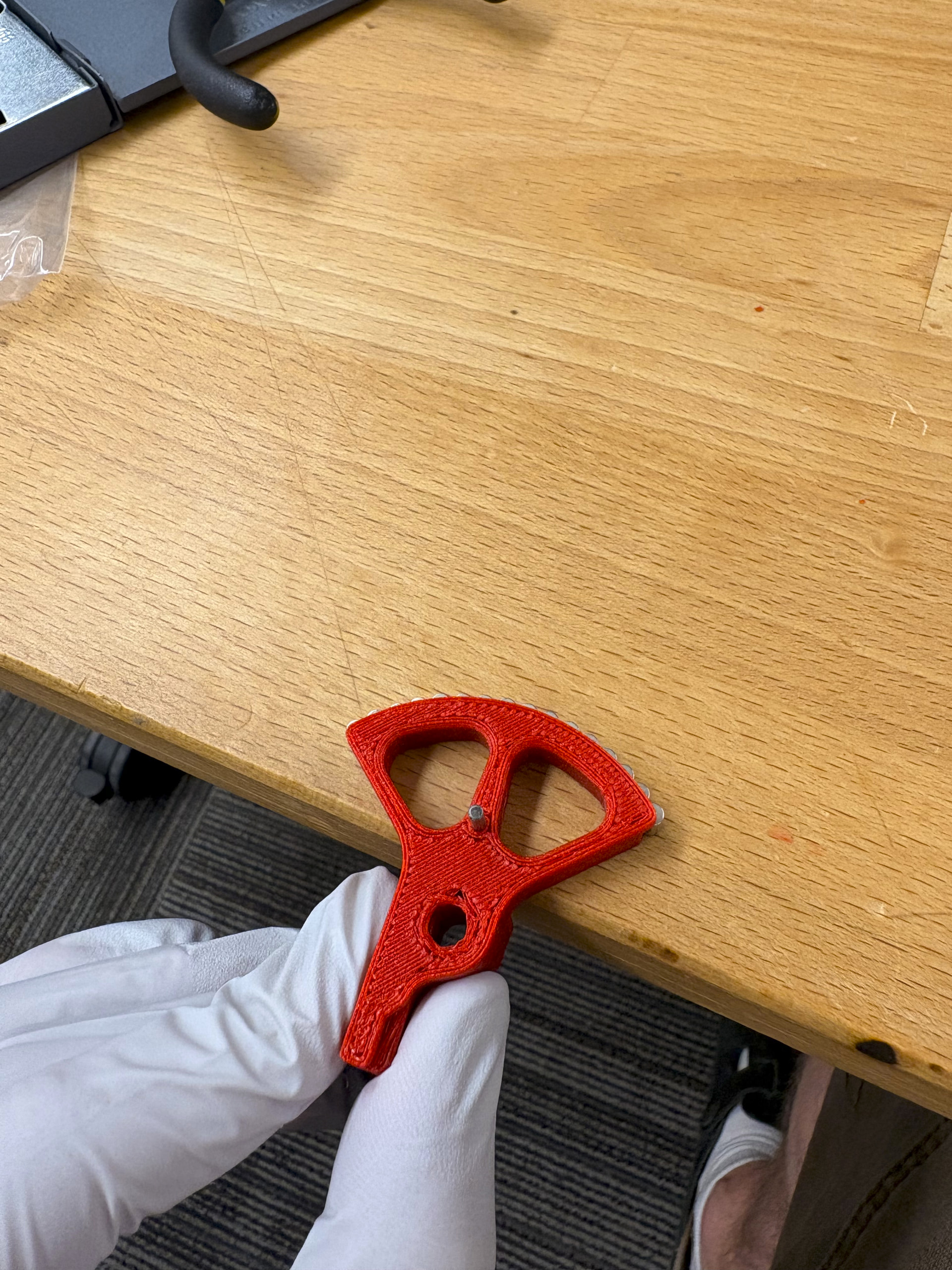
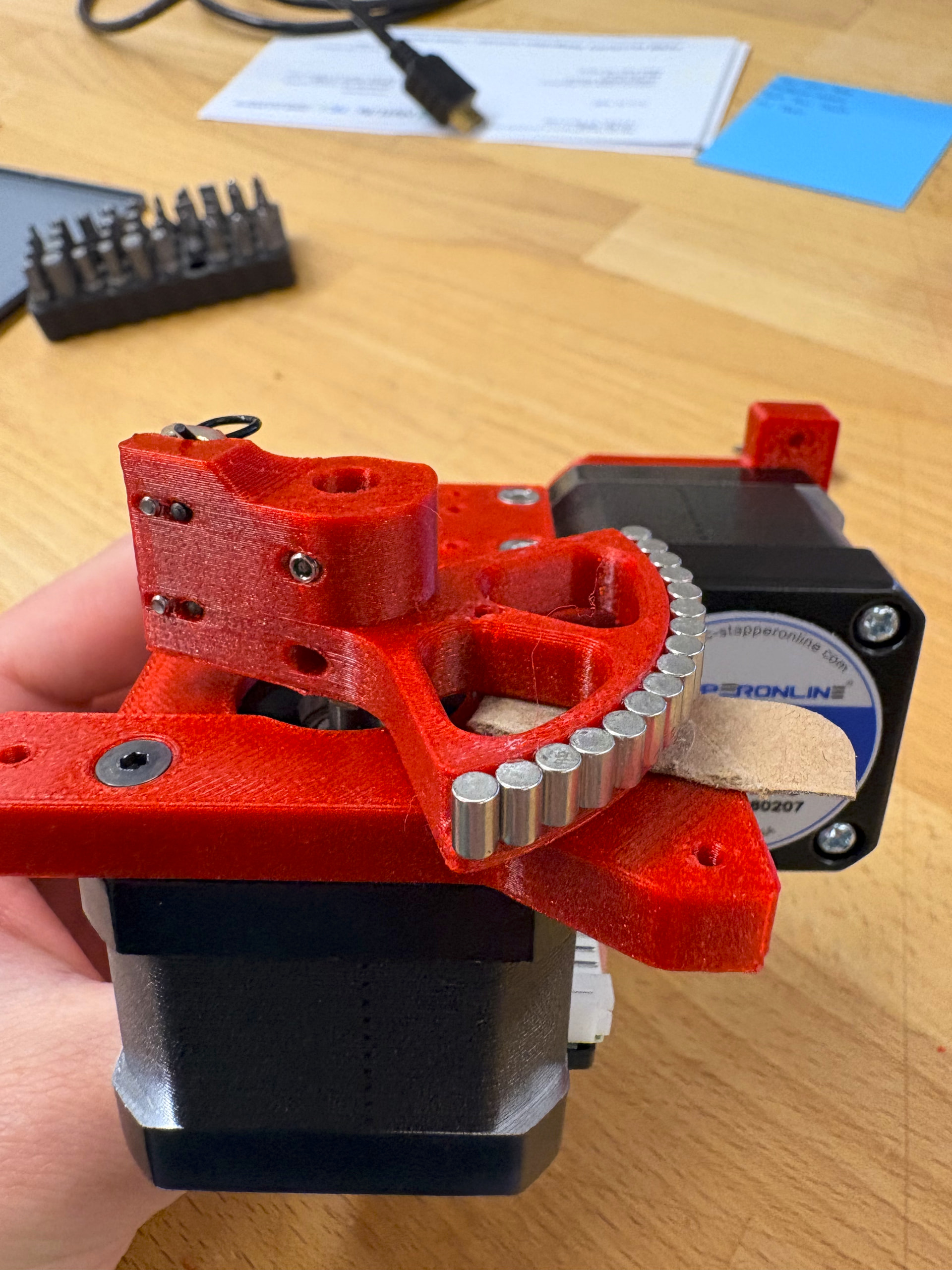
I first added the magnets and arm plates to the 3D printed horn. All of my 3D printed parts were printed on a Centauri Carbon 2 using a 0.4mm nozzle and red PLA. I ran out of the red PLA at towards the end of all my prints, so some parts were printed in white Elegoo PLA pro. I first cleaned the magnets in 90% isopropyl alcohol like I did the ball bearings. I also cleaned the horn surface using isopropyl alcohol. Once dried, I attached them to the horn using super glue. My magnets are slightly larger than the once in the BOM. I was only able to fit 16 on the horn while the original design could hold 17.
I made the mistake of handling the horns with the magnets before they were fully cured and ended up ripping the magnets off of a horn when I bumped them too close together. I would be cautious about this.
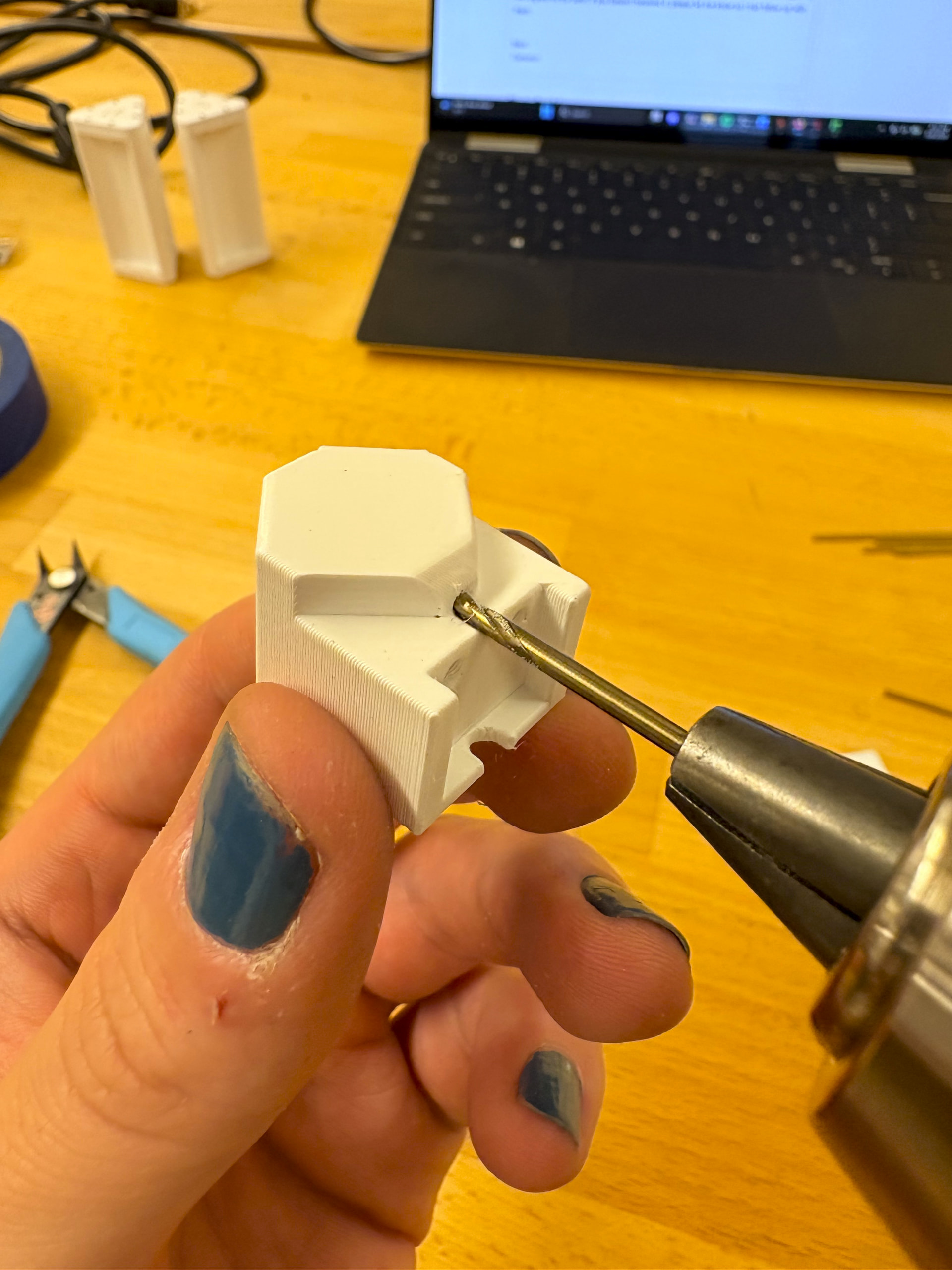
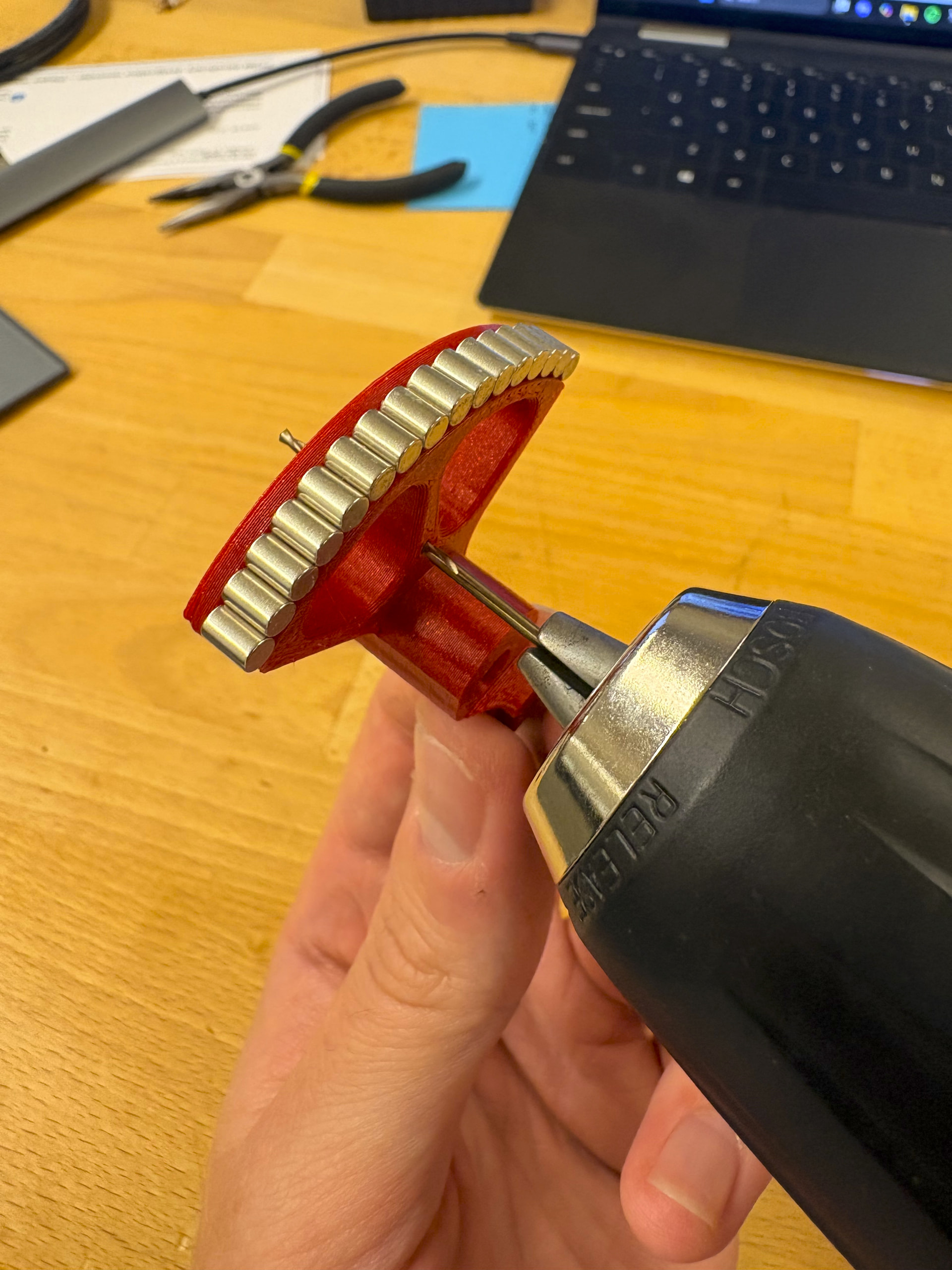
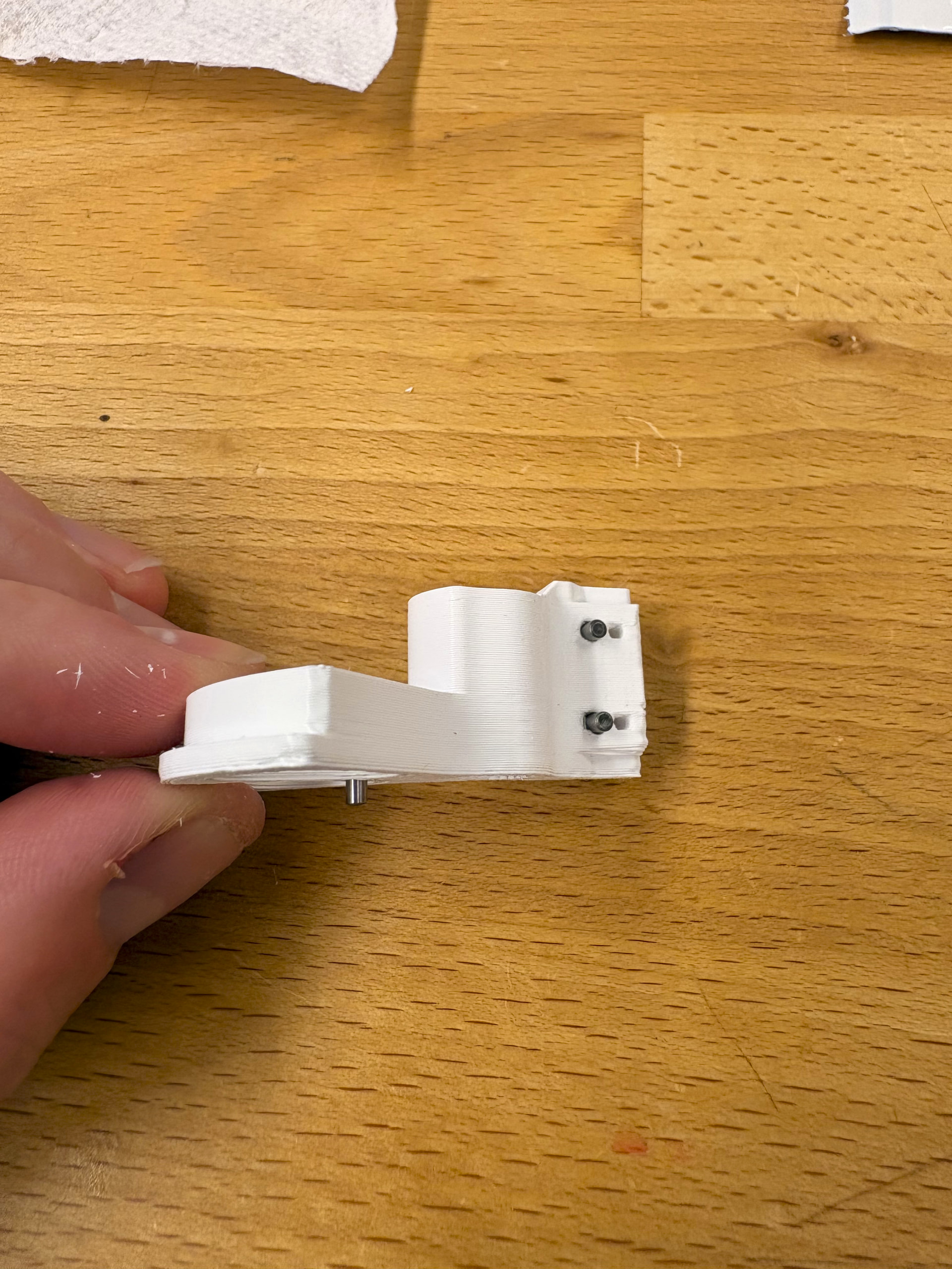
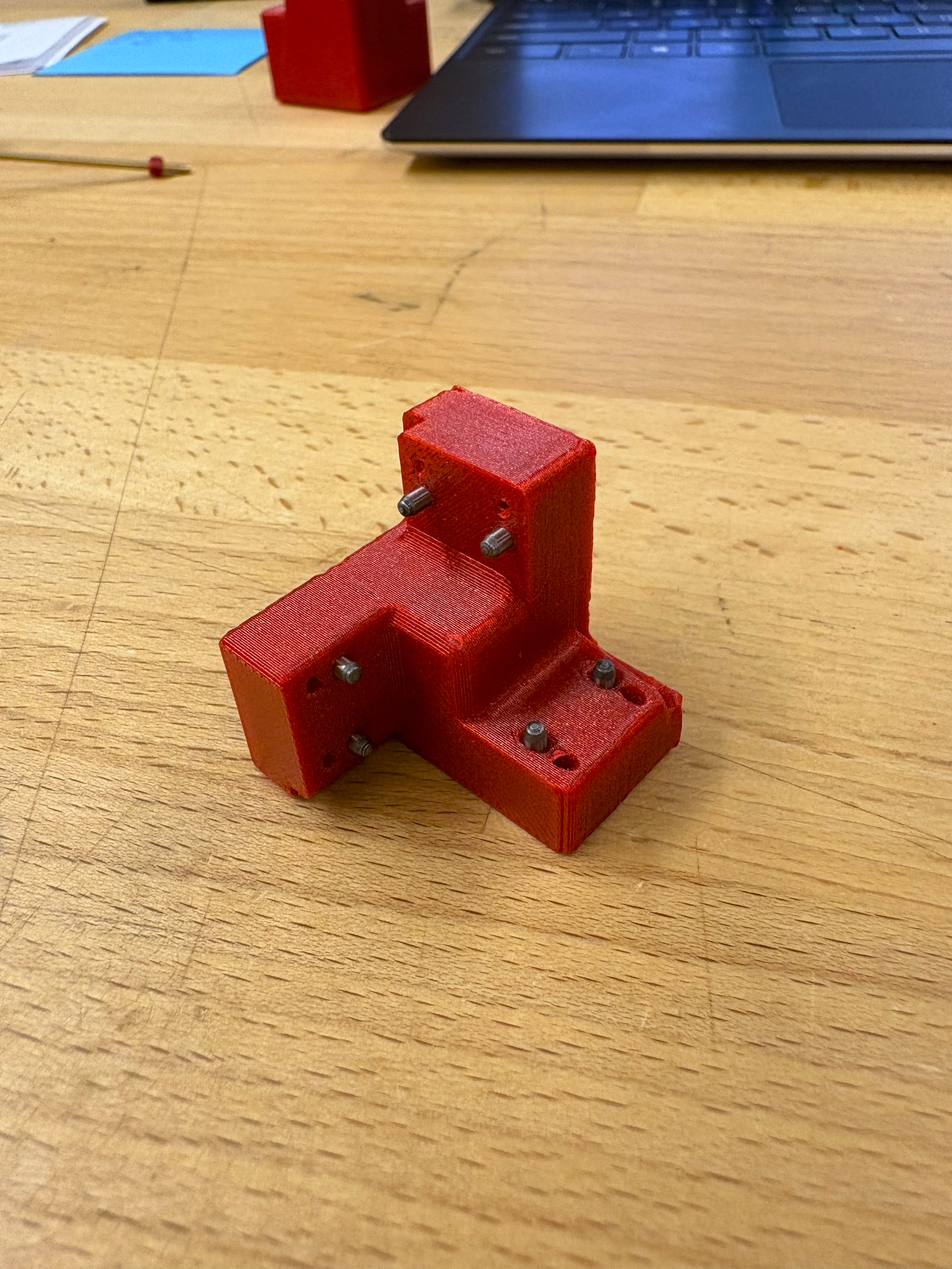
This project uses 2M 8 mm dowel rods to align pieces together before tightening them together using screws. I found that the holes for the rods was too tight straight off the printer so I had to use a 2 mm drill bit to expand the holes to insert them. This was true for all of the 3D printed components in this build.
I then took apart my ball joint arms and attached a plate to each horn. The orientation of the plate should have the shorter side of the plate facing the magnets on the horn. I then added the dowel rods and matching plates to the end effector. Note that the image of the end effector on the StepWiseDocs BOM does not match the current version. Though the link still takes you to the correct STL file.
Next, I added dowel rods to the base block. During this step it’s important not to force the rods too far into their respective holes. The CAD files show that the holes are longer than 8 mm. I pushed one of the rods too far into the base block and had to reprint the part. I then attached the motor mount to the Nema motors. Remember that 3 of the 4 screws are M3 12 mm while the fourth screws that goes in the slightly lower level is a M3 6 mm screw. I then attached each motor assembly to the base block using M3 12 mm screws.
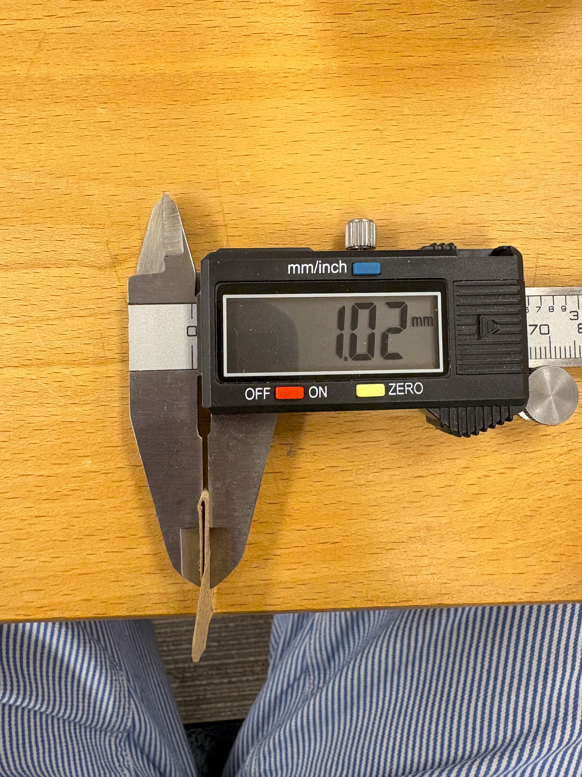
To attach the horns to the motors, its important to align the set screw holes with the flat portion of the motor rod. I then folded a piece of paper to around 1 mm thickness to create a spacer for the horn against the motor. Then I used set screws to set them at the correct distance. You could use normal screws here.
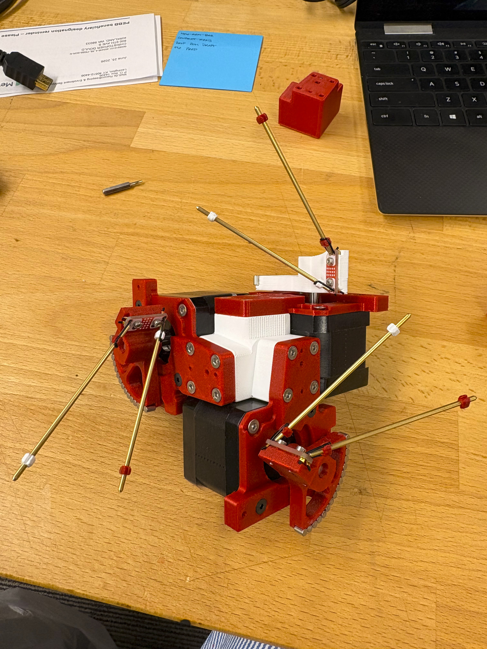
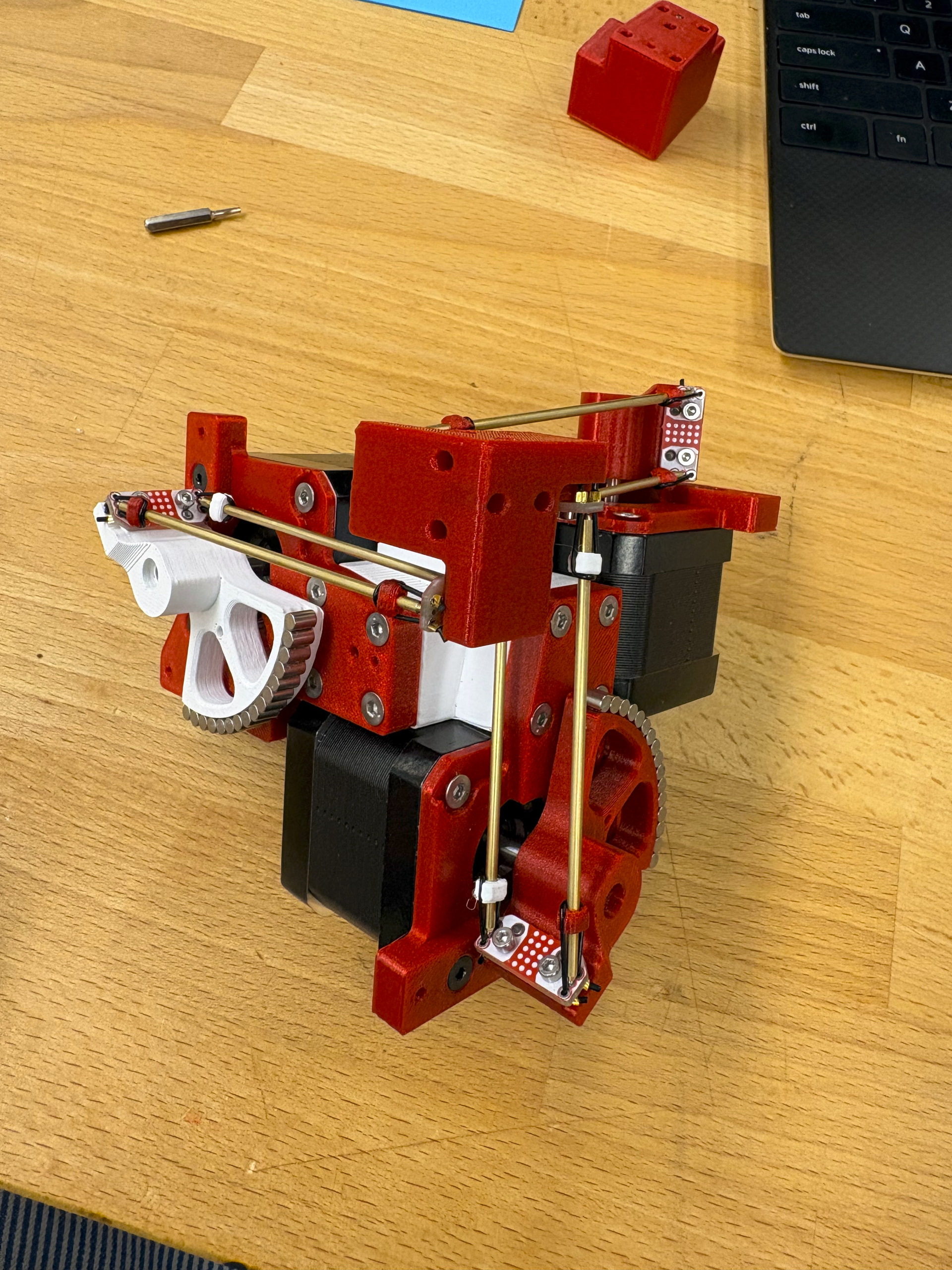
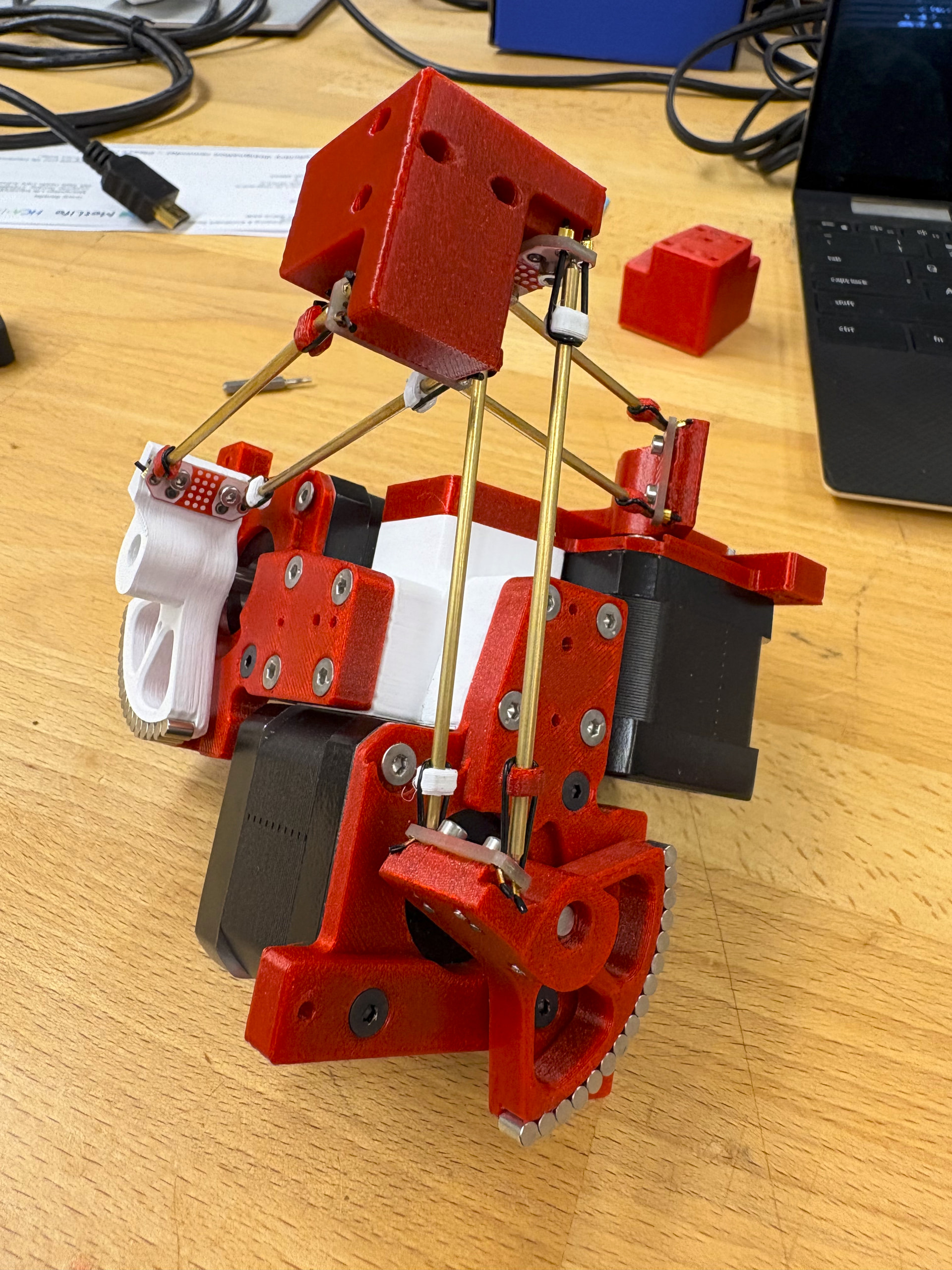
I then attached the rods to the plates on the horns and then attached the arms to the end effectors. This part was extremely finicky. A couple tips I would give would be to attach the rods to the end effector first, and then to the horns. It’s also important that the rubber band collects are properly aligned before attaching them to the assembly. I first threaded the rod and rubber band collects through the loop and slotted the PU loop into the collect before adding tension and placing on the ball joint. Tweezers are helpful to attach the last couple of rods.
Onto the electrical assembly!
I made the older model, it was actually cool.
I still have a few pcbs left, if you want. I am in NL and happy to post it to you!