More stable readings with Arduino ADC

Have you ever wonder why do you get some random noise in your Arduino ADC? Well, there could be a couple of reasons, but the most common one is an unstable voltage reference.
The ADC uses the 5V from the power source as a voltage reference when doing an AD conversion. If you measure the Arduino 5V pins, you will notice that the actual value fluctuates. So every time the Arduino performs a conversion, it compares the voltage at An pin against a different reference value.

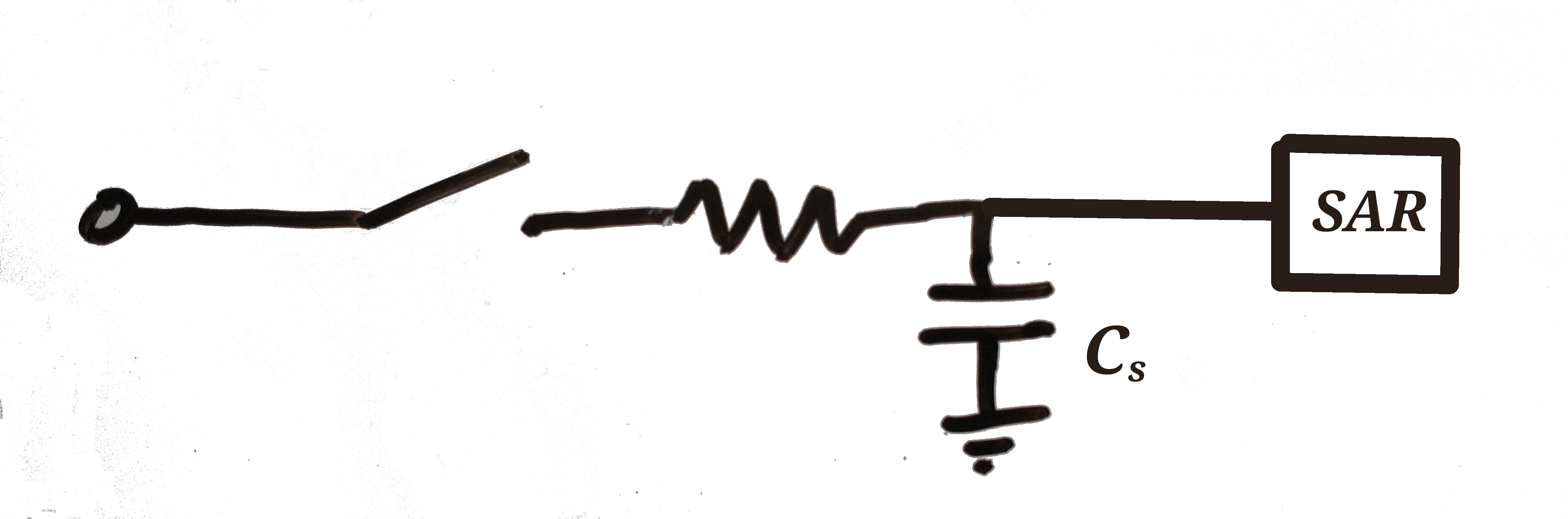
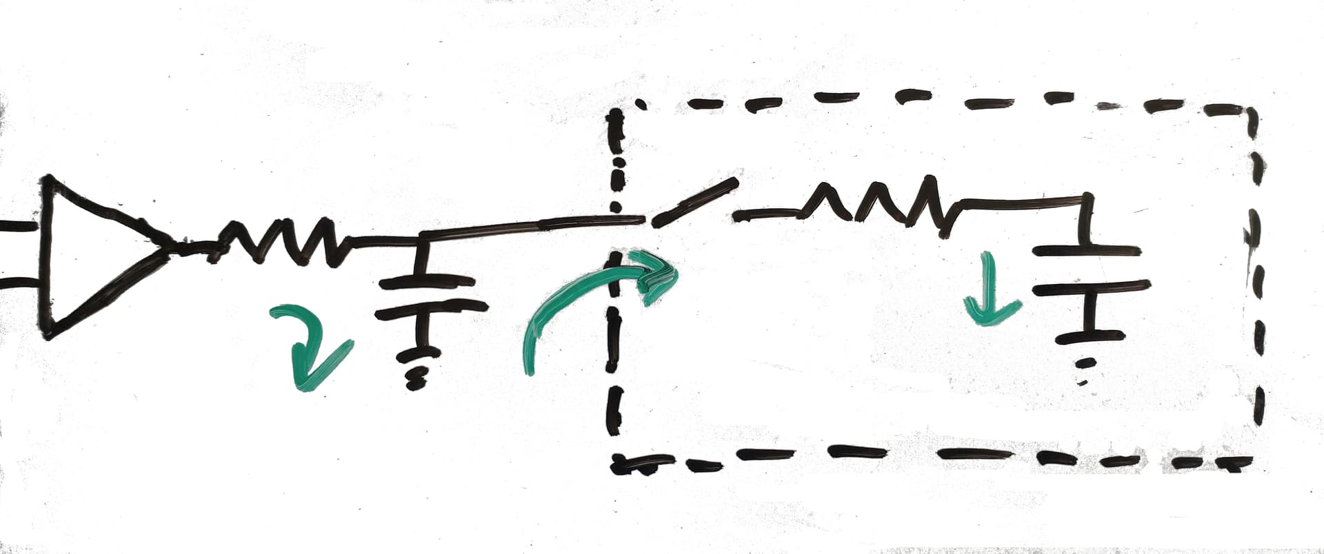
How do you solve that? The Arduino has an Aref pin to give the ADC an external voltage reference. If the voltage you are going to measure is guaranteed to be below 4V, then the LM4040 IC is a great option. This IC will give you 4.096V over a great range of temperatures and independently of the power source voltage.

image

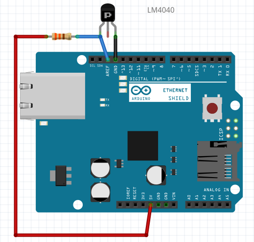
The limiting resistor is recommended to be 909ohm, but 1K works well.

After adding the external reference, you need to tell Arduino to use external voltage reference:

analogReference(EXTERNAL)

Now, another advantage of the LM4040 is that conversion from ADC value (0 - 1023) to milivolts is straight forward! Just multiply the value you get from the ADC by 4 and that is the voltage at the An pin.

With this improvement you should get more stable readings. If you still get some random noise, there is one more thing you can try. The ADC_Sleep_Mode. In this mode, the Arduino turns everything off except the ADC, performs the conversion, and wakes up. This way, it avoids interference from internal signals Timers, PWM, etc.) during conversion. This is an alternative function to analogRead() that uses the sleep mode:

int getReading(const byte port)
{
  ADCSRA = bit (ADEN) | bit (ADIF);  // enable ADC, turn off any pending interrupt
  ADCSRA |= bit (ADPS0) | bit (ADPS1) | bit (ADPS2);   // prescaler of 128
  ADMUX = (port & 0x07);

  noInterrupts ();
  set_sleep_mode (SLEEP_MODE_ADC);    // sleep during sample
  sleep_enable();  
  
  // start the conversion
  ADCSRA |= bit (ADSC) | bit (ADIE);
  interrupts ();
  sleep_cpu ();     
  sleep_disable ();

  // awake again, reading should be done, but better make sure
  // maybe the timer interrupt fired 
  while (bit_is_set (ADCSRA, ADSC))
    { }

  return ADC;
}  // end of getReading

Some of the lines of code could be moved to your setup() function, but who wants those ugly lines in the setup anyway?

If you want some more information about this, you can check this issue.

We got our ph sensor working with a precision of ±0.01 with the improvements aforementioned.

Hope this results helpful!

Pablo

2 Likes

How nice, thanks fpr sharing

Actually there are other reasons for aberrant behaviors in Arduino board analog inputs.

To understand how things go wrong, lets first review how an analog input works. We will first understand the basic setup for a normal ADC and then how this changed for the analog input built in to a microcontroller and how you might have problems with it.

Here is an equivalent circuit for a typical analog input. This much could be an ADC or the analog input of a microcontroller. We have a switch, an equivalent resistance, a sampling capacitor and a section that converts the voltage on the capacitor to a digital representation. We wrote SAR for successive approximation registor (this is where the reference voltage comes into the picture). But there are other types. For the moment we are interested in the switch capacitor network.

The way this works is that the switch and the converter run on a clock. When the switch closes, the capacitor connects to the input through an equivalent resistance. When the switch opens, the voltage on the capacitor is “held” and the conversion step begins. The period when the switch is closed is called the “sampling window”.

There are three challenges. In terms of designing an ADC or analog input, the first is how big a capacitor do I need? This is set by the thermal noise as a function of the capacitance.

v_rms =  √(kt/C) ≈ 6.4E-11/√C. 

For 16 bits of precision with a full scale range of 1 volt, we need that the noise is less than 15uV. Therefore we need a capacitor at least as large as 18pF. Since capacitance is proportional to area, in a microcontroller this takes up valuable real estate. If we settle for 12 bits, it can be 16 times smaller on each side. That is why many MCU’s have 12 bit ADCs and not 16 bit.

Second challenge, operating the ADC, the capacitor needs to come to within 1 LSB of the correct voltage withing the time afforded by the sampling window. That sets an upper limit on the size of the capacitor and resistor. For n bits of precision, we need

n x ln(2) x R x C << t\_{sampling}

For a 16 bit input at 1MSPS we might have a 500nsec sampling window, and therefore we need an RC time constant not bigger than 44nsec. In a good ADC, C is twice the minimum, about 30pF. R cannot be bigger than 1.5K ohm. Usually we make it more like 50 or 100.

Third challenge: when the switch closes, there is a large dV/dt. Without the resistor we would have a current C dV/dt. In a good ADC, we have R very small, and we add a capacitor outside the ADC to act as a charge reservoir and drive it with an opamp, like this. The green areas show how charge moves. There is a bit of an art in this; it is in choosing the external passives and opamp to support the required slew and maintain charge in the reservoir.

Okay so what is story for the analog input that is built into a microcontroller?

To make this easier to work with, microcontroller manufacturers typically make the internal resistor very large. That suppresses the current surge when the switch closes, but it also means that we cannot setup the input with a proper driver. We have to make do with whatever resistance they give us. For 12 bits they might set C_s at 8pf, and make R at least a few K ohms.

Now, how does this go wrong? There are two popular kinds of errors. We see them all the time.

The first is when a user tries to read something with a high source impedance. The humble thermistor in a divider with a large resistor is a good example of that. The RC in the math now includes the very large equivalent parallel resistance of the divider. The capacitor C_s fails to reach the right voltage in one sampling cycle. If it is read many times it eventually gets there. Meanwhile the user writes to a forum that the voltage is not stable.

The second is when the user does not provide sufficient current. The time constant goes from RC to C/I where I is the current that was allowed into the capacitor.

tau = RC -> C/I  (current limited time charging)

There are a lot of sensors that provide only tiny currents. Connecting one of those directly to your analog input gives you a current starved analog input and spooky results.

Some concluding observations:

  1. Issues with the analog input are not always something we can fix in code or by swapping voltage references. Sometimes we have to think about what we connect to it.

  2. If you need high precision, low noise, or fast voltage readings, you almost always do better to use an external ADC.

You can see some examples with spice models for the input, in my repos at drmcnelson (Dr M) · GitHub .