Hi all - Richard and I had a call today to discuss the optics and possible designs - it was super helpful for me and I think it helped narrow things down. I realize now next time I should let folks know ahead of time so we could do a broader video call, but for now I posted a link to the video on youtube.
If you want Richard’s expert explanation of single pixel cameras and all the considerations for design, I’d highly suggesting watching it!
We also felt we should include additional motors, motor controllers, and sensors in the hardware we will send to collaborators. This will allow us to all start from a common set of hardware, making replication and discussion a lot easier (rather than each of us getting a different part/motor/sensor etc.). People will of course pursue their own concepts and buy different things, but this seemed useful as a starting point.
Here is the Bill of Materials for the kits we’ll be sending out. Richard and I will be filling them out based on our discussion, but feel free to suggest/add/change.
@rbowman I wanted to answer one question which came up - Can we have each pixel (each wavelength) wait to initiate a read (a read = begin integrating) until a sensor tells it to go? This would allow us to have an encoder to trigger reading the pixel.
Answer is definitely yes. We can put while loops in the code in between the pixel reads wait which on a triggering event from the sensor. That triggering event, on the teensy 3.5, would be very very fast with little delay (in the nanoseconds range, no microseconds).
@cversek we also had a question that I needed to pass along to you - can you arbitrarily select which channel (of the 288 available) to measure, or do you have to flip through each? This may allow us to speed up the measurement by skipping certain channels. At first glance in the code, it’s not clear to me the answer, I thought you may know off the top of your head.
@gbathree
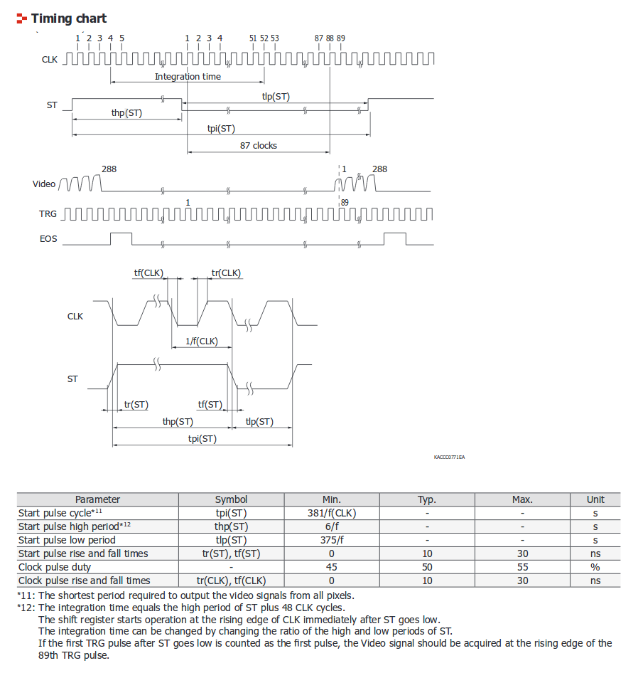
I don’t think you can address individual pixels, since the VIDEO line is like an analog shift register you always have to go through the whole array. Also, if you want to try to synchronize the measurement, you would have to trigger the integration (of all pixels) and stop it at the right times using the START signal line. To clarify, the VIDEO readout happens after the integration period ends, so you cannot time any measurements then.
Right, ok, now I got it (code below). So actually we can neither address a single pixel nor can we effectively do a while-loop wait function on a single pixel. That’s a bummer - it’d be nice to at least be able to wait between pixels (a pixel is one of the 288 channels) until a LED/detector pair was flipped. This could ensure that our timing is actually lined up with our motor, and could allow us to use more interesting motor setups (richard describes it in the video link above).
  // Step 3: Integration time -- sample for a period of time determined by the intTime parameter
  int blockTime = delay_time * 8;
  int numIntegrationBlocks = (intTime * 1000) / blockTime;
  for (int i = 0; i < numIntegrationBlocks; i++) {
    // Four clocks per pixel
    // First block of 2 clocks -- measurement
    digitalWrite(SPEC_CLK, LOW);
    delayMicroseconds(delay_time);
    digitalWrite(SPEC_CLK, HIGH);
    delayMicroseconds(delay_time);
    digitalWrite(SPEC_CLK, LOW);
    delayMicroseconds(delay_time);
    digitalWrite(SPEC_CLK, HIGH);
    delayMicroseconds(delay_time);

    digitalWrite(SPEC_CLK, LOW);
    delayMicroseconds(delay_time);
    digitalWrite(SPEC_CLK, HIGH);
    delayMicroseconds(delay_time);
    digitalWrite(SPEC_CLK, LOW);
    delayMicroseconds(delay_time);
    digitalWrite(SPEC_CLK, HIGH);
    delayMicroseconds(delay_time);
  }
Hey, I’ve uploaded a PDF of my doodles to GitLab in case it’s useful in addition to the video (should be higher resolution pictures at least). I’ve also added a few annotations to try and make it a useful thing even if you don’t want to sit through my slightly rambling explanations…
Re: lens choice, for the “collection” lens (gathering light after the mask) a plastic asphere might be good - e.g. 31 AP 29 from Comar. This would probably give us the best possible intensity at the detector, if we go with the plan of focusing the light down onto a diffuser.
For the imaging lens, we could probably get away with something like a Comar 40 PC 16 if budget is an issue; it won’t be as nicely corrected, but would probably do for proof-of-principle. That would give a reasonably large/zoomed-in image, which may not be perfect but is probably good enough as a starting point. I have some reasonably good mounts for these that can be 3D printed.
For a photodiode circuit, the easiest option is to bias the detector (e.g. with a battery) and use a resistor to convert current into voltage - but this is noisy, I think, and might not work very well. Better performance would come from using an amplifier of some sort in transimpedance configuration which I think could still be done at reasonable cost.
You could probably use hardware gating mechanisms to time when the ST pin signal is triggered, but I (not knowing that much about motor control or single-pixel cameras) would think that the simplest scheme would be to have the mask position change fully under the control of the microcontroller so it can synchronize the integration times between the movements thus eliminating concerns about motion blur.
@cversek Good point - we could set a trigger to the ST pin. Again, this is something we’re just going to have to play around with and see what happens.
@rbowman I’m game for getting the 31 aP 29 and Comar 40 PC 16 as starting points - they aren’t super cheap, but cheap enough to buy for the initial testing group which is great. I’ve added them both to the BOM and they are ordered.
I spent some time today looking for integrated pin photodiode / amplifiers, but couldn’t find anything reasonable. What about something very simple like this →
Upsides - it’s cheap, easy to use, and I can get them tomorrow and so can most people. Linear voltage output.
Downsides - it requires a diffusor (I’ll just cut a bunch of them and send them in the kit. It definitely will max out in high light conditions.
I think this can work, if I include a diffusor - what do you think?
Hey, that all sounds good - I don’t think maxing out is likely to be an issue (we can just dump some more light) - it’s more sensitivity I’m worried about. I reckon the board you link to should be good for starters. If light’s too bright we can just chuck a bit of greaseproof paper in the optical path behind the mask, that will get rid of some power!
Cool - ok I ordered those. I think the longest delay (possibly up to a month) is one of the lenses from Comar. Otherwise I got 6 of everything on the list.
I’ll let you know when it’s all in and I can ship it out to everyone - then we can actually get to work on it!
I’m buying these additional items through Our-Sci - is it ok with folks if I include Our-Sci as a sponsor on the GitLab page?
At long last, they have arrived!!! The specs made it to my house!
Last thing we need are optics, then I can ship. I have all your ship addresses from that survey I did before, but in case anything changed please let me know.
It’s a pain Comar are no longer keen to ship just a few optics - that was always one of their major selling poiints for me If we want something cheap that will get us started, the lenses from Google Cardboard are actually not a bad start - they are longer focal length than I’d ideally like, but they are super cheap and 25mm diameter. We could even experiment with using two of them back-to-back which would trade quality for light (probably a good trade, at least initially).
I can’t see why not. They will not be ideal, but I’m hoping they’ll be “good enough”… It’s possible that getting 3 per kit would help, so we can use 2 of them between the mask and the sensor for greater focal power. If they’re only $1 each, that might be OK?
Nice I’ve ordered a few of the lenses myself so I can play with more of them. Decent, cheap lenses are hard to find, so I’m hoping these are as good as they look!
I have the Spec hardware working as a Spectrometer with the Teensy using some tweaked example code, but I’m not sure how the data processing will work to create an image.
Right now, it’s just shooting an array of 288 values to Processing for visualization. Will we want to store the image data for later processing?

 If we want something cheap that will get us started, the lenses from Google Cardboard are actually not a bad start - they are longer focal length than I’d ideally like, but they are super cheap and 25mm diameter. We could even experiment with using two of them back-to-back which would trade quality for light (probably a good trade, at least initially).