Build your own instruments! DIY data loggers with no custom PCBs

This is Great :slight_smile: Do you guys come to AfricaOSH? I wish to hear more from you…

I’m afraid not. We would have to trade several visits to our fieldwork sites for a trip like that. To be honest we only get to one conference per year, and that’s usually the GSA because so many of our academic partners also go there.

But we have made the entire project accessible via the website and the pub. There is a Google translate button on the upper right corner of each page. But I have no idea how well it actually translates those build instructions.

Thanks. I did read a little bit of the project today. Didn’t have much time though. I couldn’t find explanation on how you retrieve data from the data logger. I will go through your project slowly. But I can’t wait to find the answer to this. Can you tel me in one sentence how you collect the logs from the device. Do not worry about technical words. I have some knowledge in electronics and embedded systems.

The code saves the data on an SD card as time-stamped comma separated text. Simply disconnect the battery, and replace the sd card with a new one. Then open those data files open directly on your computer with any spreadsheet like Excel or open office.

One of our biggest problems with commercial sensors is that they make you buy expensive download cables, and then pay for custom software just to view the data. Both of those steps are un-necessary.

A visiting researcher dropped by our humble basement workshop with questions about the physical skill level students would need if they added one of DIY data loggers to their environmental curriculum. I figured the easiest way to cover that was to simply build one, while they recorded the process. The result of that three hour session is now available on YouTube:

1 Like

Great approach. We have also developed this ultra simple and low cost version of our Attiny sensor boards. aka 8Bit Mixtape aka CocoMake7, with a similar approach. it doesnt even need an “arduino”, the Attiny85 is widely available, it can be re-programmed using an audio signal (no drivers needed, and communicate to an app through mini-jack) and also has USB-HID capability for sending numbers as keyboard." 234".
A true open hardware project should be easy to redesign, repurpose etc. and not rely on buying dedicated boards.

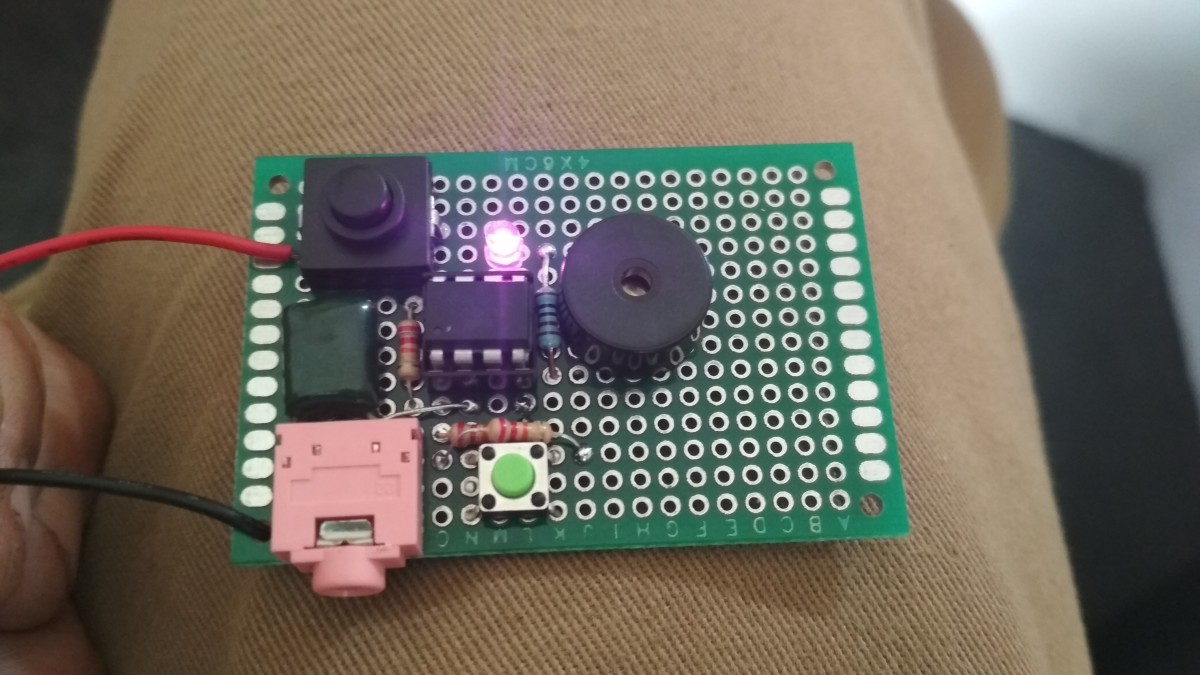
But the same board can still be made with custom PCB for a workshop and souvenir. can save time during the session.
See this:

2 Likes

We love the tinys too!, and your project is a brilliant example of how much can be done with those little uCs. But for our data logging application they just didn’t have enough i/o lines for the number of different sensors we need to use (and now adding display screens too!) The 328p’s built in I2C peripheral frees up significant memory on the chip for data processing which has also become important for us to handle noise suppression in turbulent environments. The little pro mini clones we based our logger on are now so generic that you can find dozens of variants on ebay & allibaba so I think of them as simply breakout boards for the 328p processor rather than as Arduinos…

While the Arduino logger core is generic, the surface deployments tend to use the 4" housing (which is easy to build) while the underwater deployments (about half of the current fleet) use the 2" body style. Usually those deployments are too deep to record with our little point & shoot camera, but we recently did an install in a coastal outflow that was shallow enough to capture a clip of the method we use to anchor the sensors into place.

In the first video we are placing the anchor in the fresh water, with extension rods to move the actual sensor into the zone where saline water (the silty brown layer) in intruding into the system. Like the housings, all the pieces of the deployment system are made from zip ties and cheap plumbing parts that anyone can buy at any hardware store:

and once the flow sensors are installed, we check on them occasionally to see how they behave different flow conditions.

These units are accompanied by other sensors for temp, pressure ,etc.

We’ve added a new Tutorial to the projects website that might be of interest to people for their own projects:

This is the third in our series about using shift-out and unused analog lines to drive SPI displays. The primary reason to use this method is to save power in data logging applications that need to run for years at a time. When you drive the pin-power line down the screen is completely disabled and draws no current.

Posted a new build guide to youTube: https://youtu.be/SPeUWtE0pIYt
which walks through mounting the logger “stack” on a platform with batteries. Like others in the series, this was a result of a walk through with someone who’s building Cave Pearl loggers for use on their own independent project. Will add another vid on sensor caps and epoxy potting when time permits.

cheers!

Added a new tutorial video to the set: how to pot sensors & build waterproof cable connectors

New “EDU version” of the Cave Pearl Logger released for 2019

Dr. Beddow’s instrumentation class has been building the 2016 version of the Cave Pearl datalogger for more than three years, and feedback from that experience motivated a redesign to accommodate a wider range of student projects while staying within the time constraints of a typical lab-time schedule. The rugged PVC housing from the older build has been replaced with an inexpensive pre-made box more suitable for “light duty” classroom project deployments. The tutorial includes a full set of youtube videos to explain the assembly. We hope this simplified build supports other STEM educators who want to add Arduino-based experiments to their own portfolio of activities that develop programming and “maker” skills.

1 Like

A teacher friend asked us for faster build that is less dependent on soldering because they don’t have the budget for that kit. So we’ve developed a “minimum version” of the 2019 classroom logger using pre-made Dupont jumper cables to reduce the build time to about 1 hour. I’ve also added support to the code base for using the indicator LED as a light sensor, so they can use the logger with their existing curriculum right away.

This version of the Cave Pearl is probably the best starting point for people building their very first Arduino-based data logger.

1 hour Logger Project for the Classroom [Feb 2019 Update ]

You can use a Pro Mini (or any other Arduino with an Atmel processor) to measure temperature to 0.0025 C or better using only the mcu. I think this is the best “No-Parts” temperature method I ever noodled around with:

‘No-Parts’ Temperature Measurement with Arduino Pro Mini

This method generalizes to any other processor with a hardware driven watchdog timer, and should be easy to adapt for other projects.

This is fantastic work you’ve done! I’ll need something similar to a cave pearl soon, and decently accurate temperature measurement is a problem. For the narrow range of temperatures that we’re usually interested in, I think it comes down to calibration, which I’m still grappling with.

If you are working with a tight range of temps this no parts technique might not be the best option for you. The oversampling I developed last year gives a similar resolution, but with far less noise in the signal. see:

Have you any thoughts on how to best go about calibrating a sensor?

This is really impressive!
It’s both simple and robust!
One thing I saw the group is working on the calibration of sensors, which in many project is considered as a “next step”, something secondary… or a complete black box!
congrats!

Yeah, calibration is really the line that separates the hobbyist sector from the much smaller group of people that are trying to use these little open source controllers for research. The frustrating thing about it is the engineers advice is always the same " buy a more expensive sensor and use their calibration". Which is fine if you are doing a standard task, under standard conditions. But most of the researchers are trying to do things that the sensors were not designed for in the first place - For example, most of our temperature sensor IC failures have been because of pressure at depth… which of course they were never designed to withstand. So calibration is always required.

1 Like

I’ve been developing a new method for reading thermistors with the Input Capture Unit on pin D8. Micro-controllers count time much more precisely than ADC’s measure voltage, so this new approach delivers more resolution than 16-bit oversampling in about 1/10th the time & power